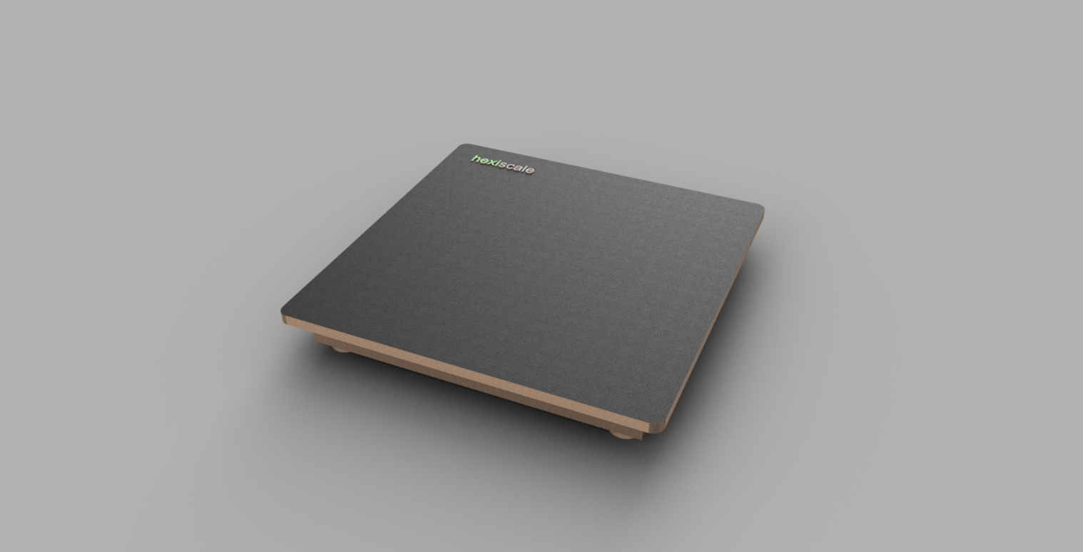
This project describes the design and construction of a bathroom weight scale, it features the Hexiwear IoT device for its core functionalities. Hexiscale consist of load sensors that are used to measure the weight of a human or any other object that is placed on the platform. Measurements are achieved by a careful interface of the load sensors to the Hexiwear device through its IO pins. Successful measurements are transfered via the built-in hexiwear's Bluetooth Low Energy (BLE) to an Android mobile application where it is being displayed to the user. It was an awesome idea as well to have the captured measurement synchronized to a cloud service, hence by clicking synchronize on the android app, captured weight data are published to Wolksense IoT cloud service. Wolksense has beautiful analytic features for published data from IoT devices. With this in place, users can view the curve of their weight loss or gain. Check the video to fully have an idea of what this project is all about.
The IdeaI had always wanted to measure my weight and monitor the changes over time automatically and have a cloud system that can analyse these weight data by just a click of a button. And it would be advantageous for maintaining a healthy life style by checking against obesity. So I thought of designing and constructing Hexiscale. Hexiscale is a device that measures your weight just like the regular bathroom scale in our homes, but comes with a feature of having the readings displayed on a mobile phone. This exposes the possibility of managing these measured data as a log and finally gets synchronized to the cloud, giving you a platform for viewing reports of changes in weight overtime.
How it Works
Before we get started the flow remains as simple as first to use weight sensors connected in such a way that a maximum of 200kg can be measured, secondly voltage signals produced by the sensors are amplified and converted to digital signal using a suitable analog to digital converter. Thirdly converted digital signals are read by hexiwear device and transmitted via BLE connection to an android powered mobile phone or tablet PC and finally get data from the phone or tablet PC published to an IoT server (Wolksense). So with this in mind lets go get started.
Hexiscale consist of the following components.
- Four (4) load sensors
- Hexiwear
- Hexiwear Docking Station
- HX711 (24-bit AD converter)
- 350mm x 350mm Wooden platform
The load sensors used in this project are half bridge sensor types, wich are designed to measure a maximum load of 50kg each. The half bridge feature delivers an advantage of the possibility of combining two half bridge sensors in a wheatstone bridge arrangement to form a full bridge, thereby increasing the maximum load that can be measured. In the case of full bridge, the maximum load becomes 100kg.
Typically, load sensors works by having linear changes in resistance of a strain gauge due to an equivalent strain introduced by a load. In a half bridge sensor, a network of two load cells or strain gauges which forms two variable resistors are arranged as described in the diagram.
This arrangement ensures that, when a load is applied on the sensor one of the resistors experiences compression and at the same time the other experiences a tension leading to positive and negative changes of resistance in the respective variable resistor cells. this ensures that no resistance of the resistors are the same when a load is applied. this means voltage drop across each variable resistors are the same when no load is applied. Load cell can either be used as a half bridge or full bridge. To use the load sensors in any mode, they have to be arranged such a way to form a wheatstone bridge. The diagram here shows the connection of two load sensors in a wheatstone bridge arrangement, which apparently can sustain a maximum of 100kg. More about wheatstone bridge here.
1 = R1/R2 = R3/R4, Vo = 0 when balanced. and V1 is a known and constant voltage
This arrangemnet is necessary so that at no point the output voltage Vo is 0 when a load is applied on the sensors. When a load is introduced, Vo changes in correspondence to the appliead load, hence Vo at Load L is said to be the corresponding load voltage. Vo varies as the load linearly. It is Important to mention here that the noticeable changes of voltage across Vo as a result of change in resistance of the strain gauges in the load sensor due to an applied load, is very minute. This makes it difficult for most devices to detect this changes as the load sensor is experiencing strain. So what next? here comes the rescuer! the HX711 24 bit ADC load sensor amplifier with serial interface.
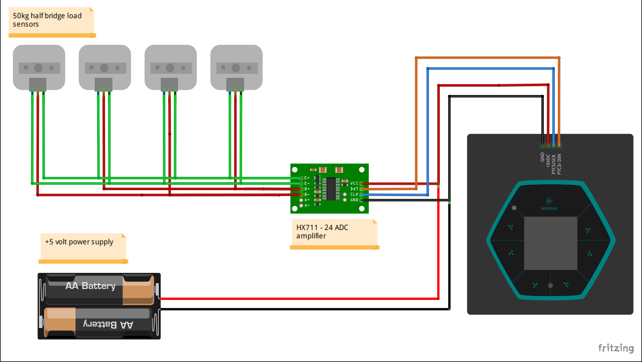
HX711 is and ADC device designed specifically for weighing systems and also used mainly with wheatstone bridge sensor arrangement. It has a configurable gain of 32, 64 and 128. It operates under a range of 2.25VDC to 5VDC and also has two differential input channels A and B. To interface the load sensor connected in a wheatstone bridge arrangement as described previously to the amplifier module, Vo is connected to B- and B+ of the HX711 module. B+ and B- are the differential input to the amplifier with a gain of 120 by default. E- and E+ are terminals for positive and negative excitation voltage. Now from the wheatstone diagram, V1 terminals are connected to E- and E+. So with this connection in place and module powered, data is ready to be read from the serial interface by a processor or a microcontroller. In our case Hexiwear wins the place.
Reading the DataHX711 implements a serial protocol to read its data, though very simple and straight forward. pin DAT and SCK are used to read the converted data from HX711, gain selection and power down control. Pin DAT outputs serial data and SCK is used for clocking out the data. When output data is not ready to be read, at this point the DAT digital pin is kept HIGH so as the SCK pin should be kept low. When data is ready to be read, DAT goes low the this should indicate that data is available. At this instance, 25 to 27 clock pulses must be sent via SCK pin to retrieve 24 bit serial data over DAT pin. The 25th clock pulse is used to determine the gain of the amplifier for the next read operation. The 25th clock pulse selects the gain on channel B only to 128. For more details check the HX711 data sheet for its full description and operation.
To move further, from the simple process flow i mentioned earlier the next thing is to hook sensor reading to hexiwear. Hexiwear is one of the most advanced development kit i have ever worked with and it is quite impressive of the loads of sensors that came with it. Thanks to the hexiwear dock station that breaks out the pins of the K64 ARM cortex M4 processor in Hexiwear. The diagram below shows a generic break out of the I/O pins that were used to interface Hexiwear and HX711 serial pins.
The break out pin indicates PTC5 which served as clock to Hx711 and pin PCT3 as DAT_IN connected to DAT pin of HX711.
Programming HexiwearTo get the readings from HX711 , the mentioned HX711 serial protocol was implemented in Hexiwear. Hexiwear can be programmed via the OPenSDA communication on dockstation. Hexiwear uses RTOSs like freeRTOS and mbedOs 5. In this project ARM mbedOs 5 was used to run Hexiwear. ARM mbed is a powerful online IDE that you can use to develop your applications that can run on several ARM boards without code changes. I found this amazing as it is very simple to use and truly helps quicken time to market. ARM mbed online IDE currently runs mbedOs5 which has loads of reusable libraries.
To program on mbed IDE is very simple. You simply compile your written code, have your Hexiwear dock station with Hexiwear device in place connected to your PC. After a successful compilation a bin file is downloaded. Simply drag and drop the downloaded bin file into the Hexiwear dock station drive that should appear as one of your drives when you connect the dock station, then press the k64 reset button on the dock station to start the program on Hexiwear.
The snippet below shows how the data from HX711 is read. I modified the serial port sample in Hexiwear code repository in mbed IDE.
#include "mbed.h"
float _scale;
DigitalOut myled(LED_BLUE);
DigitalIn HX_DOUT(PTC3);
DigitalOut HX_PD_SCK(PTC5);
Serial pc(USBTX, USBRX);
long offset = 0;
long ReadWeight(void);
//double getGram();
uint16_t getGram();
long getAverageValue(int times);
int main()
{
   offset = getAverageValue(20);
   int i = 0;
   pc.printf("Hello World!\n");
   while (true) {
       wait(0.5f); // wait a small period of time
       pc.printf("%d \n", getGram()); // print the value of variable i
       i++; // increment the variable
       myled = !myled; // toggle a led
   }
}
long ReadWeight(void)
{
       long Count;
       unsigned char i;
       HX_PD_SCK.write(0);
       Count = 0;
       while(HX_DOUT.read() == 1);
       for (i=0;i<24;i++)
       {
               HX_PD_SCK.write(1);
               Count=Count<<1;
               HX_PD_SCK.write(0);
               if(HX_DOUT.read() == 1) Count++;
       }
       HX_PD_SCK.write(1);
       Count=Count^0x800000;
       HX_PD_SCK.write(0);
       return(Count);
}
uint16_t getGram(){
   return ((getAverageValue(20) - offset))/1000;
}
long getAverageValue(int times){
   long sum = 0;
   for (int i = 0; i < times; i++)
   {
       sum += ReadWeight();
   }
   return sum / times;
}
And here is the screen short of the reading from the load sensors. To use the serial example with the dockstation, mbdSerial driver was downloaded and installed on my development machine.
And here is the physical setup of hexiwear and the four sensors under the wooden platform to measure 200kg maximum load. The circuit diagram for this connection is available at the schematic section. The schematic shows the sensors connection in full bridge parallel.
The main idea of this project is to preview measurements on a user's smart android phone or tablet. In other to achieve this, bluetooth LE module was used in hexiwear to send measurements from the scale to the android mobile application. The mbed hexiwear BLE library was utilised to add BLE functionality to hexiscale. Hexiwear Code with BLE implementation is available at the code section. The BLE implementation in Hexiwear uses pressure Service to transmit data to Hexiscale android application. Hexiscale android app was built using Hexiwear android sample code and wolksense android sample application on github. Wolksense web service api implemented in the sample code was reused in Hexiscale android application to add the functionality of publishing data to the wolksense cloud service. Getting data published requires a sign-up first on the wolksense platform. Every other details about wolksense can be found here. Full source code of the Hexiwear code can be obtained here.
Wolksense web view for published data.
Calibration is one of the most important part of this project. Without calibration, measured data would be meaningless. To calibrate, all that is needed is a known weight. When designing and constructing this project, i could not get hold of a scale to help calibrate the hexiscale. But here is the simple trick. from the basic knowledge of physics, we understood that
Density = mass/volume -------- (1 ). if density and volume are known, then we can get the mass. With this formula, we also know that 1 litre of water is 1kg; proof:
1000litres = 1cubic meter; and the density of water = 1000kg/m3 from equ. 1
mass = density * volume --------- (2). therefore the mass of a liter m:
m = 1000 * 0.001 = 1Kg. So with this knowledge i setup two 75cl bottles filled with water on the hexiscale. From theory, this means 1.5litres = 1.5kg. I had found out before that each 75cl bottle is around 40grams. Putting this into consideration, total weight of a filled PET bottle becomes 0.79kg. At no load, it read 8766239, at 1.58kg load (1.5+0.04 +0.04) it read 8805015. To get the weight per digital step (resolution), it is safe to use the following relationship between values.
(8805015 - 8766239) * k = 1.58 therefore, k = 1.58 / (38766) = 0.0000407574.
In hexiwear code implementation, the data been transferred by the onboard BLE is the difference between the measured value and the offset value (the offset value which is the value at no load, is automatically calculate by finding the average of 20 readings). Acquired data is scaled by 1/1000 so as to have value that can fit in 16 bit integer variable which can be transmitted in a single function call by the BLE api. The android code uses the resolution calculated above and the scale, to reconstruct the actual final result for display.
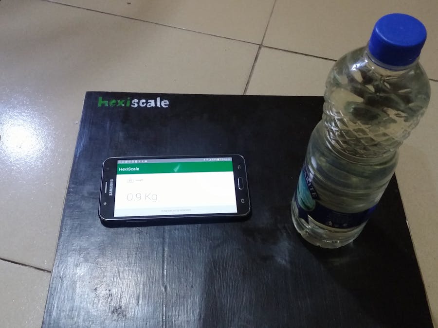
Having done all this, to verify and test the theory, four filled 75cl bottles where arranged on the hexicale for measurement. From theory of course the scale readout should be 0.79kg* 4 = 3.16 and the result of the measurement came out as displayed in the image below.
Well the result did not come out as expected, but it was very close. So far this is not a likely acceptable process of weight scale calibration, though it did the trick. In the real sense, weighing systems should use a known weight for calibration. This method is derived and is prone to errors as it encompasses too many assumptions so it is not advised to use this method when designing a scale that would be thrown into the market. I hope to improve on this design later in future by using a proper method of scale calibration.
I hope to seeing your comments and advice on how this project can be further improved. Thank you.


_t9PF3orMPd.png?auto=compress%2Cformat&w=40&h=40&fit=fillmax&bg=fff&dpr=2)
_3u05Tpwasz.png?auto=compress%2Cformat&w=40&h=40&fit=fillmax&bg=fff&dpr=2)


Comments
Please log in or sign up to comment.