The idea behind this project is to create a device able to drive an actuator based on the gesture of the hand's fingers.
The project is specialized on recognizing streaming images of the hand taken by the raspberry-pi camera.
The data set of the images used to train the model was created ad hoc with images taken from the Raspberry Camera only (not other devices) with a neutral background.
The model is based on the transfer learning of the Inception v3 model, customized to handle the project requirements. The last layer was removed from the Inception v3 model and a few layers were added to be customized with the new dataset and to provide the output for just four cases.
The model was trained with the images collected and pre-classified earlier on a desktop (32 Gb ram + GPU). Once the model was trained and tested, it was exported to the Raspberry Pi.
Create datasetThe aim of the project was to identify the position of my finger(s).
Therefore, it was created a dataset of images where the fingers where in four different positions {'nothing', 'one finger', 'more than one finger', 'hand closed'}.
The images below shows an example for each case.
The position of the hand was always upside-down.
Create the modelThe model used is based on the technique known as transfer learning. From the pre-existing model already fully trained (the Inception v3 model ) the last few layers were removed and extra few new layers were added. (https://www.tensorflow.org/api_docs/python/tf/keras/applications/InceptionV3)
Below the code to customize the added layers to the model.
last_layer = pre_trained_model.get_layer('mixed7')
last_output = last_layer.output

#creating a model using the previous model without the last few layers
x = layers.Flatten()(last_output)
# Add a fully connected layer with 100 hidden units and ReLU activation
x = layers.Dense(100, activation='relu')(x)
# Add a dropout rate of 0.2
x = layers.Dropout(0.2)(x)
# Add a final sigmoid layer for the classification of the 4 status
x = layers.Dense(4, activation='softmax')(x)

model = Model( pre_trained_model.input, x)The training was based only on the dataset of the images and to it was added some variability to force the model to generalise. This variability or diversity (known as data augmentation) allows to increase artificially the number of the examples for the training and to improve the quality of the classification.
training_datagen = ImageDataGenerator(
      rescale = 1./255,
      rotation_range=40,
      width_shift_range=0.2,
      height_shift_range=0.2,
      shear_range=0.2,
      zoom_range=0.2,
      horizontal_flip=True,
      fill_mode='nearest')
The model was fitted with just 20 epochs, enough to fit the model and avoiding overfitting.
history = model.fit(
            train_generator,
            validation_data = validation_generator,
            steps_per_epoch = 5,
            epochs = 20,
            validation_steps = 5,
            verbose = 2)
The accuracy of the model was quite good, especially for the validation dataset (which is made of real images without the variability (data augmentation).
Once the model was good enough, it was saved and exported.
model.save("C:\\gits_folders\\Tensorflow_Lite_embeded\\raspbery\\enzo_02")All the steps described so far are on the Jupiter notebook available at the link below:
Deploy the Model to Raspberry PIThe model training and testing was performed by a quite powerful desktop. Once these steps were concluded, the final result had to be moved to the Raspberry PI.
The Raspberry PI is supposed to perform only the inference from the images streaming taken from Raspberry PI camera (which is computational so, much less intensive than the training).
export_dir = "C:\\gits_folders\\Tensorflow_Lite_embeded\\raspbery\\enzo_02"
loaded = tf.saved_model.load(export_dir)

converter = tf.lite.TFLiteConverter.from_saved_model(export_dir)
converter.optimizations = [tf.lite.Optimize.DEFAULT]

tflite_model = converter.convert()
tflite_model_file = 'enzo02_converted_model.tflite'

with open(tflite_model_file, "wb") as f:
    f.write(tflite_model)
Following the code, the model is saved in a file ("enzo_02"), which can easily copied from the desktop to the Raspberry PI filesystem. Then, it can be read by a python script running on the Raspberry PI.
from tflite_runtime.interpreter import Interpreter
....
interpreter = Interpreter(args.model)
  interpreter.allocate_tensors()
  _, height, width, _ = interpreter.get_input_details()[0]['shape']
The full script is available at the link:
Below an example of how to lunch the script:
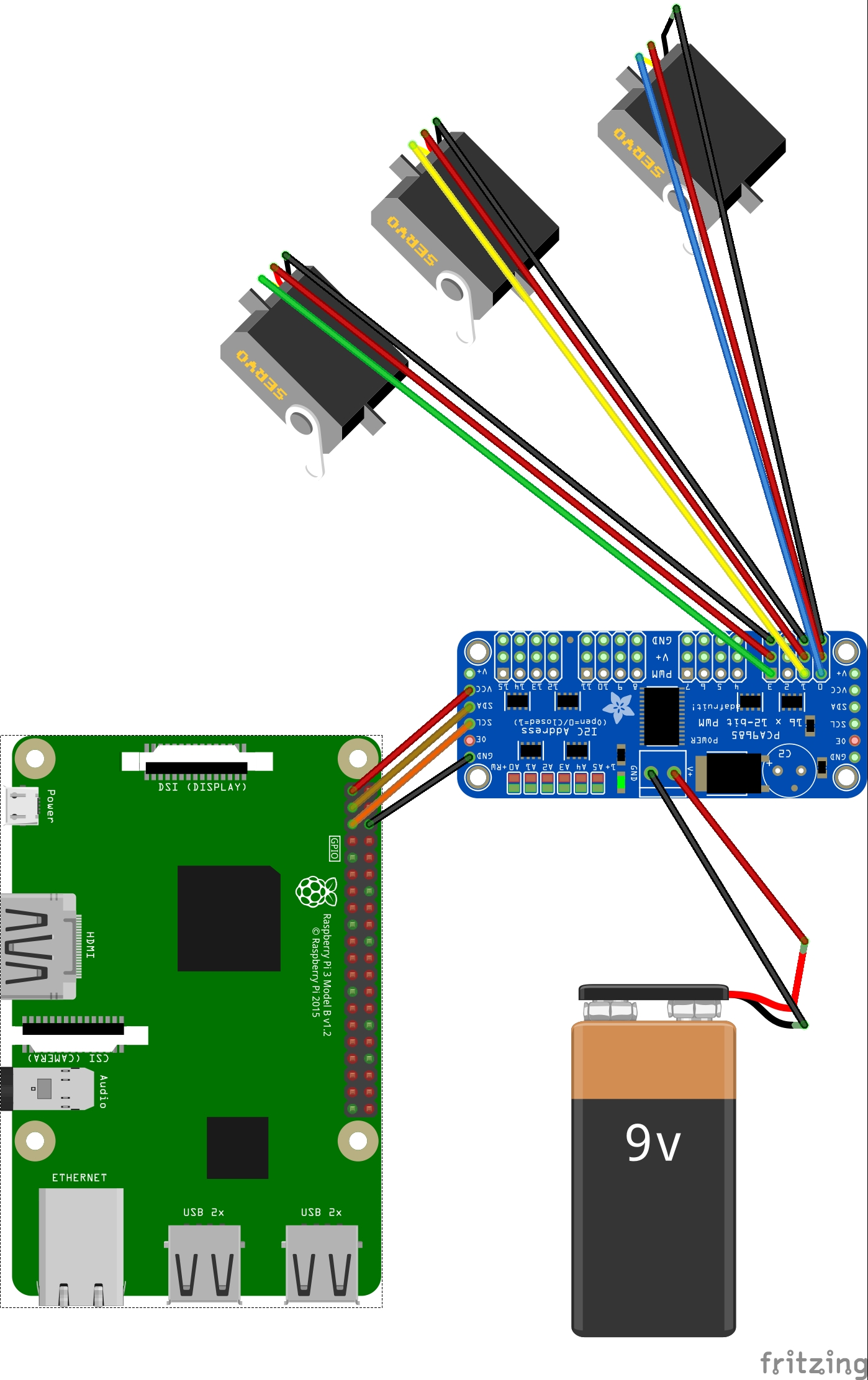
python3 classify_picamera_servo.py --model ./enzo01_converted_model.tflite --labels ./labelsThe electric circuit is quite straightforward. The Raspberry PI 4 with the camera are the core components. They collect the video stream and perform the inference using the deployed model. Then, based on the inference results a signal is sent to the PCA9685 which actions the 3 servos accordingly.
The PCA9685 workload to action the 3 servos is supported by an external battery of 9v.
The 3 flags have been created with Polymorph material. The Polymorph is a special type of plastic with a fusing temperature of around 60˚C, which can be moulded into any shape when it is heat up with boiling water. Once it is cooling, it becomes a very tough nylon-like polymer. As it is a thermoplastic, Polymorph can be re-heated and thermoformed numerous times.
Its use is very simple, you just need to put some amount of polymorph into a glass of water, warm it up in a microwave for a couple of minutes (until the polymorph becomes transparent).
Then just take it out of the water and start to mould it into the desired shape.
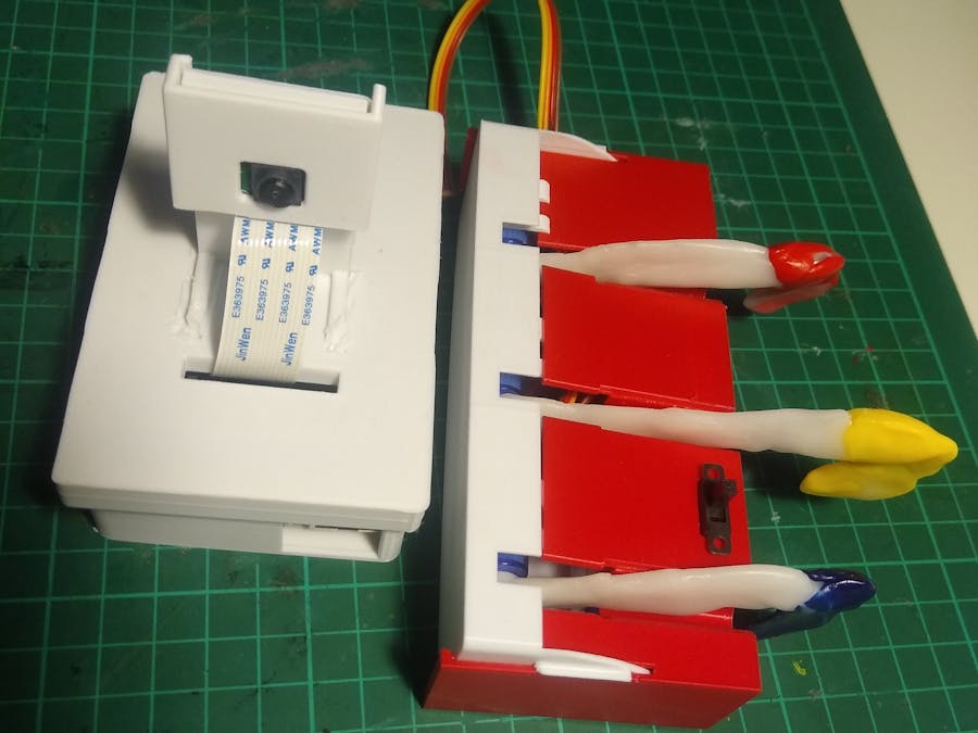
In this project, the polymorph was given the flag shape and added a servo arm (for each of the 3 flags). Once they cooled they created a unique structure with the server arm inserted. Therefore, it was easy to attach them to the servos.
We differentiated the flags by adding coloured Polymorph, so each flag has a different colour.
3D Printing the Enclosures and Final BuildingThe final building is quite straightforward, 3D print the servos holders and the Raspberry PI/camera holder using the.stl files on the attachments section.Attach each flag to one servo, and insert the servos into their holder.
Then, insert the Raspberry Pi and its camera into the enclosure.


_t9PF3orMPd.png?auto=compress%2Cformat&w=40&h=40&fit=fillmax&bg=fff&dpr=2)


Comments
Please log in or sign up to comment.