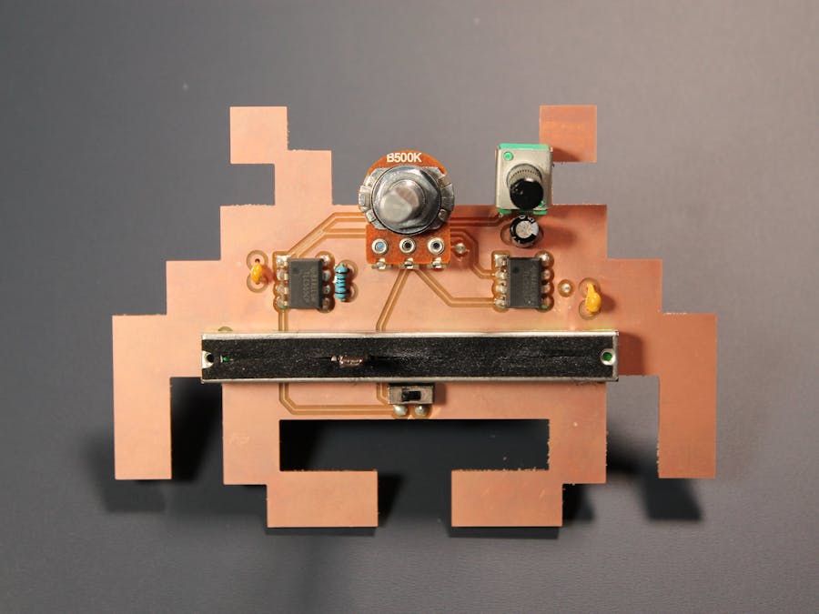
Ahhhhh, the good old days, when the bleeps and bloops of video games emitted from your local arcade and Atari reigned supreme. There is nothing like the sound that is heard ringing from Pong, the wakka wakka wakka of Pac-Man, and the beautiful squiiink of your blaster in Space Invaders. The Atari Punk Crab creates these nostalgic sounds and then some with the squeal and wahwah of pulsating electricity created by two 555 timers.
The Atari Punk Console is based on a circuit first published in a Radio Shack booklet in 1980, dubbed the "Sound Synthesizer". It was invented by designer Forrest M. Mims III. More recently, Kaustic Machines renamed the circuit the "Atari Punk Console" because the low-fi sound resembled the Atari games from the 80s. The circuit is an astable wave oscillator that drives a monostable oscillator to create a single square pulse. If none of that last sentence made sense, no worries, grab the parts, throw them on your breadboard and you'll soon understand what a "monostable square pulse oscillator" sounds like.
The Atari Punk Crab is just another step in my exploration of the 555 timer and all the things we can build with this stellar little chip. We will be doing both breadboard and PCB designing in this tutorial.
Let's Lay it Out on Our BreadboardTo start, pull out all your components and double check you have what you need.
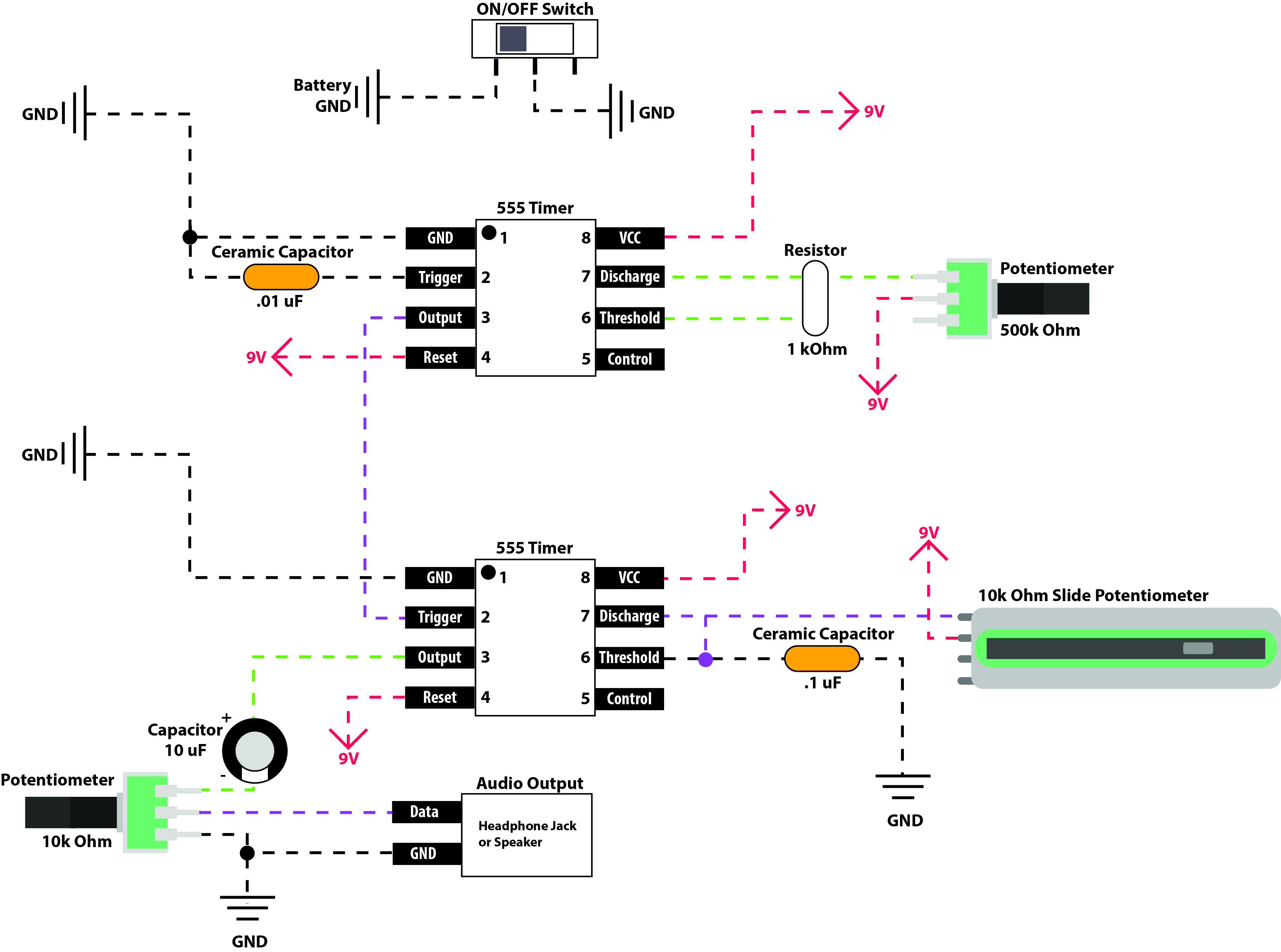
Use the diagrams below to place the components on your breadboard. I've provided two options, one in a more traditional schematic view and the other laid out on a breadboard. Feel free to use whichever version you understand more!
Once you've placed the components, attached a speaker and powered "on" the circuit you should begin to hear the pulsating squeals of the Punk Console, bringing on the 80s nostalgia. If you can't hear anything try adjusting the 10k Potentiometer (the volume knob) and continue playing with the other potentiometers to get find the right sound.
And Now, My Favorite Part... PCB Design Time!With our circuit working on the breadboard it's time to translate it into Patchr and make a PCB. As you work on laying out your circuit board, be sure to use the above diagrams as reference as well as your breadboard punk console.
First things first, create a new project and start drawing the footprint of your PCB. I chose to make mine the Atari Crab from Space Invaders.
Now that our board footprint has been drawn (I know you created something pretty stellar), let's place our components. I tried to keep everything even, making sure to make room for larger parts like the 500k potentiometer and the giant slide potentiometer. I also place the On/off switch at the very bottom in order to stay out of the way during an intense jam sesh.
The 555 timer comes in a generic PDIP package (8 pins with 4 evenly spaced on 2 sides) so we can use any 8-pin through-hole IC, I chose the ATtiny85 for this layout. A few helpful shortcuts to speed up your layout:
- Copy & Paste: Select a component on the board, press Command + C, Command + V
- Rotate a Component: Select the component then select and hold one of the corners of the bounding box or Command + R
Now we will use our breadboard design and the schematic diagrams above to route our PCB! Here are a few helpful keyboard shortcuts:
- Switch to top side of the PCB: Command + 1
- Switch to bottom side of the PCB: Command + 2
- Rotate a component: Command + R
- Toggle pad view vs component view: Command + P (removes all the components icons to reveal the component footprints)
- Show ghosted image of routes on the opposite side of the PCB: Command + H
- Route colors: Red = power, blue = ground, orange = bottom layer, green = top layer
Once you have routed your PCB, select export at the bottom left and you can either send it on out to Patchr Manufacturing, mill it at home or kick it old school and export it as PNGs for a nice Ferric Chloride bath.
AssemblyWith your components and PCBs delivered it's solder time! Use your Patchr project as a resource and the circuit diagrams to help you as you put things together. Take note of the polarity on the 10uF Capacitor as well as the positive and negative leads of the battery.
All that is left is a jam sesh, have fun playing around with this super fun synth!
If you want to skip the breadboard and designing I've also attached the PCB design files so you can manufacture your own.


Comments
Please log in or sign up to comment.