

Hardware components | ||||||
 |
| × | 1 | |||
 |
| × | 1 | |||
 |
| × | 1 | |||
 |
| × | 14 | |||
 |
| × | 4 | |||
 |
| × | 1 | |||
 |
| × | 7 | |||
| × | 1 | ||||
 |
| × | 1 | |||
| × | 1 | ||||
 |
| × | 1 | |||
Hand tools and fabrication machines | ||||||
 |
| |||||
 |
| |||||
My story:
Having played violin for a long time, I thought it would be fun to combine my love for music with the skills I have been learning in my course. I wanted to have a way to indicate the note value, as well as display whether the note is sharp, flat, or in-tune. I also wanted to have a way to display the frequency.
For the display, I chose to use LEDs for the notes and sharpness/flatness, and a hex display for the frequency display. I wanted to apply concepts I had been learning in class in a new context.
This project was my first time coding in Python, so I struggled a lot to get used to Cloud9, the Python syntax, importing files, and structuring code. It also took me a really long time to determine the desired frequency ranges I wanted to use to denote for different sharpness/flatness levels. Unfortunately, the amount of time I spent troubleshooting and learning Python means that my project isn't 100% fully functional yet, and I wasn't able to spend the time I wanted creating a casing for the device.
Current progress of project:
Using a random frequency generator, the device can successfully display the correct frequency value on the hex display and light up the corresponding LEDs. However, the frequency detection code is currently not accurate (it reads significantly lower than the test tone). In the video below, for example, the test tone is 1000 hz, but the program reads it as ~40 hz. I had a lot of trouble with different audio and analysis packages, and definitely need to keep improving this aspect of the project.
Build instructions:
1. Collect all hardware components
2. Solder the pocketbeagle pins (see image)
3. Connect the USB adapter to the breadboard (see image) and female USB into the adapter. Then, add the PocketBeagle so that header pin P1_1 is in hole a1.
4. Connect the LEDs to the following pins. Use a 100 ohm resistor for each pin, and make sure the shorter wire of the LED is connected to ground. In the orientation of the device, A-F LEDs should be arranged from left to right, and flatter to sharper should be arranged left to right (flatter, flat, green/in-tune, sharp, sharper)
LED pins:
blue_led_A="P2_2", blue_led_B="P2_4", blue_led_C="P2_6",
blue_led_D="P2_8", blue_led_E="P2_10", blue_led_F="P2_18",
blue_led_G="P2_20", yellow_led_flatter="P2_22",
yellow_led_flat="P2_24", green_led="P2_33",
yellow_led_sharp="P2_35", yellow_led_sharper="P1_34"
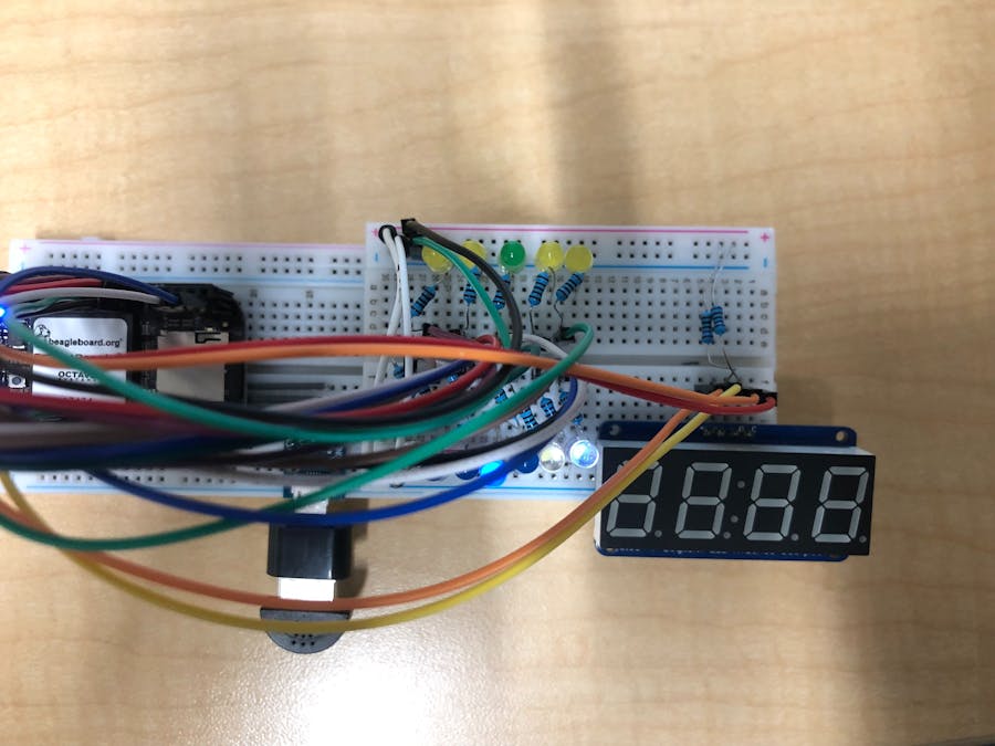
Here is an of what the LED setup looks like:
5. Next, connect the HEX display. Connect the "+" pin to a 3.3V input and the "-" pin the ground. Connect C and D to i2c bus 1 (P2_9 and P2_11 respectively). Add two pull-up resistors: these will connect from either D or C to a 3.3V rail on the breadboard.
6. Double check the Fritzing diagram to make sure you are wiring correctly! Note: the Fritz diagram only has the "in-tune" LEDs (ran out of space), but repeat the same process for the note LEDs.
Operation instructions:
1. Run code
2. Play tone for 3 seconds
3. LEDs and hex display will show frequency and note value
Link to video of device:


Comments
Please log in or sign up to comment.