


Hardware components | ||||||
 |
| × | 1 | |||
 |
| × | 1 | |||
Software apps and online services | ||||||
 |
| |||||
I sat in my dorm, drowning in the miasmatic stench of Welch’s Fruit Snacks and unwashed laundry. It was 3am, and I was 27 hours into my Road to Global Elite stream. I hadn’t left my desktop in over 15 hours and hadn’t slept for double that.
At this point, most of my viewers weren’t interested in my CS:GO ranking, but in my eligibility for the world record for the longest uninterrupted gaming session in human history. Unlike them, I still cared about my rank and was subsisting on nothing but the passionate pursuit of this goal...and a 7-eleven Big Gulp filled with 5-hour energies.
Hours turned into a day as I scored victory after victory, failure a distant memory as my goal fell within my reach. As my clock struck thrice I was only a few games from joining my mentors and drinking the sweet ambrosia of that legendary status. Unsurprisingly, my next match was on Dust II. My viewers were getting bored and I felt the monotony of endless matches setting in. So, in an effort to keep the donations rolling in, I decided to play aggressively for a few kills. As the match started I bolted for the infamous underground cavern, quickly dispatching players whose reflexes couldn’t compare to those of a man hopped up on nothing but energy drinks and unadulterated passion.
I had what at the time seemed to be an unbeatable strategy. I would camp the entrance and annihilate any opposition that ran past while offering defense to my team. As I lined myself up to the edge of the doorway with pixel precision that the most skilled players would tremble at, I attempted to strafe against the wall to minimize my profile and moved forward.
It wasn’t until after the gunshots and spontaneous outcry of my team that I realized what happened. In my semi-lucid state I had walked forward, rather than right, exposing my full model to enemy gunfire.
Without their most skilled player we lost the match and my streak had ended. As I lost 80% of my viewers and took a hit to my rank, something inside me snapped and I passed out on the spot. Now, 2 months later, I still haven’t revisited the game.
If only I hadn’t been up so long.
If only I hadn’t nodded off for just that millisecond.
If only there was some sort of spontaneous stimulant to keep me awake in that critical hour.
I would dwell among the CS:GO legends of yore
Despite all of the time that passed, my failure still suppressed my self-esteem. That is until the gracious Dr. Ray Simar afforded me an opportunity to redeem myself. In the moment that this project was assigned, I, Kieren Boyd, and the rest of the RGBOIS decided to create the EPIC RGB GAMER HYPER ELITE LIGHTING PRO V2 2021 LIMITED Unlimited Performance Edition - Red Wired USB - WIFI 6 Lite Edition ERGONOMIC.
-Inspiration written exclusively by Adam Bobak
Thanks to our product, no gamer will ever fall asleep during an intense grinding session! Designed to be attached to most modern headsets, our intelligent lighting system calmly iterates through every color in the RGB spectrum when in ambient mode, offering a nice decorative fixture to your stream setup. However, when in GAMER MODE, the light cycle kicks into overdrive, magnifying its loop speed by 10, guaranteeing that nobody within a 200 meter radius will be able to sleep for the duration of this effect.
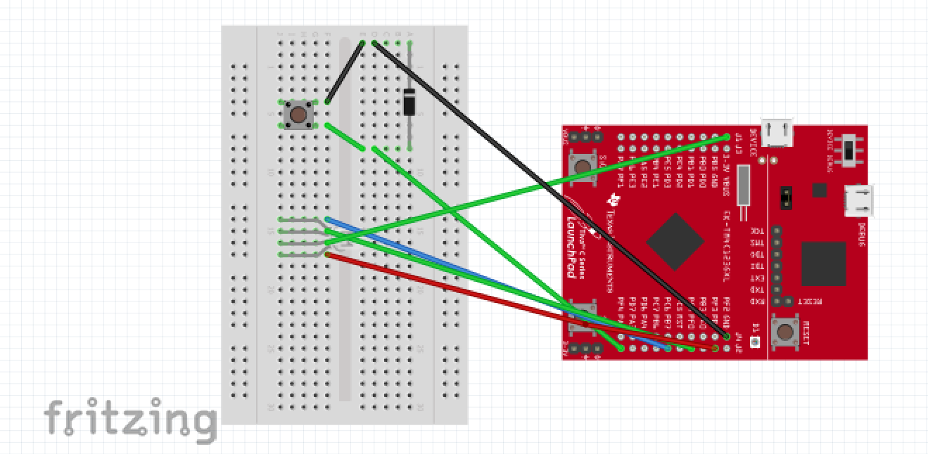
How does one activate GAMER MODE you may ask? Well, it's a simple but effective method that is perfectly equipped for a dozing individual. You see, our lightboard is equipped with state-of-the-art gyroscopically responsive technology that precisely responds to changes in the board’s angular orientation. That means that any significant change in one’s head angle, such as a position characteristic to a seated sleeper, will be met with an irresistibly beautiful light show that is sure to awaken the wearer from their dreary stupor. To sweeten the deal, our R&D department spent arduous days equipping the seizure lightshow machine with a usb adapter that allows users to divert power to the board directly from their desktop.
- V2.0: Thanks to popular demand and the opinions of our dedicated fans, the EPIC RGB GAMER HYPER ELITE LIGHTING PRO V2 2021 LIMITED Unlimited Performance Edition - Red Wired USB - WIFI 6 Lite Edition ERGONOMIC now comes with a feature that allows the user to engage GAMER MODE at the push of a button, perfectly setting the environment for an EPIC gaming session.


Comments
Please log in or sign up to comment.