In many IoT scenarios, it is possible that automation will be required to physically move something. In order to do this, you will need to utilize some type of motor. In this example, we will control a single DC Motor using the L293DNE chip and the Raspberry Pi 2 running the Windows IoT Core operating system.
Materials Required
- Raspberry Pi 2 running Windows IoT Core
- Pi Cobbler with Ribbon Cable (optional)
- L293DNE chip
- DC Motor (6v motor)
- One 4xAA battery pack (to power the motor)
- Breadboard
- Various M-M Jumper wire
Hardware Setup
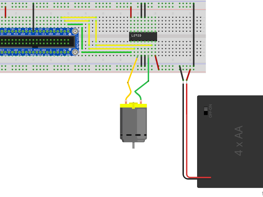
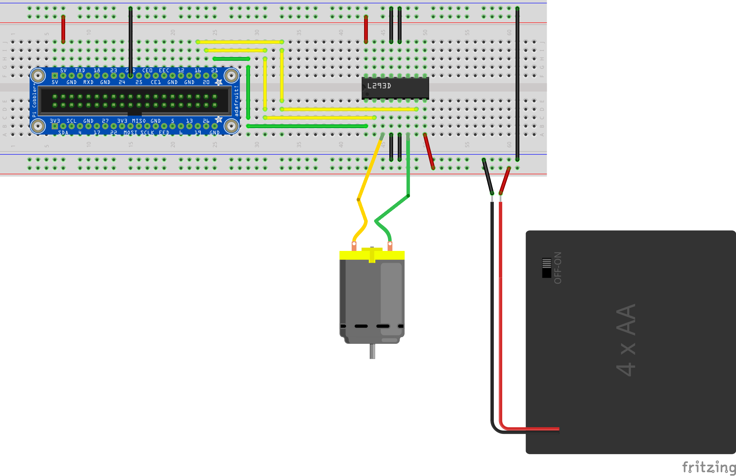
Single DC Motor Control Wiring Diagram
L293D Pin Out Diagram from the Datasheet
Wiring Details
- Cobbler 5v to the Breadboard Power Rail #1
- Cobbler GND to the Breadboard Ground Rail #1
- Breadboard Ground Rail #1 to the Opposite Breadboard Ground Rail #2
- L293D Pins 4,5,12,13 to Breadboard Ground Rail
- L293D Pin 16 (VCC1) to Breadboard Power Rail
- Cobbler Pin 21 to L293D Pin 1 (1,2EN)
- Cobbler Pin 20 to L293D Pin 2 (1A)
- Cobbler Pin 16 to L293D Pin 7 (2A)
- Battery Pack Positive (Red wire) to Breadboard Power Rail #2
- Battery Pack Ground (Black wire) to the Breadboard Ground Rail #2
- L293D Pin 8 (VCC2) to Breadboard Power Rail #2
- One motor wire (interchangeable) to L293D Pin 3 (1Y)
- One motor wire (interchangeable) to L293D Pin 6 (2Y)
DC Motor Control Wiring
LD293D IC
This project takes a simplistic look at achieving Bi-Directional control of a DC motor. There are multiple ways to implement this solution, and this is just one of them. The L293D chip has the ability to control two motors, but in this case, we will just be using one side of the IC to control one motor. This IC works off of 5V logic, which is fed to the chip through Pin 16 or VCC1. The DC motor requires more amperage than the Raspberry Pi can dish out, so we feed it with a different power source by using an external battery back through Pin 8 or VCC2. In order to control the motor, its enable pin must be set to High, in our case we are using the left hand side of the motor control IC, so that would be Pin 1 (1,2 EN). The microcontroller inputs (1A or pin 2 and 2A or pin 7) are used to control the direction the motor will spin, and the motor output pins (1Y or pin 3 and 2Y or pin 6) engage the motor in response to the signals from the microcontroller.
DC Motor Control table from the Datasheet
Software
In this solution, a new blank Universal Windows application was created and named PiDCMotorControl. A reference to Windows IoT Extensions for the UWP was added. In order to create the UI, replace the MainPage.xaml listing with the following:
UI Definition:
<Page
    x:Class="PiDCMotorControl.MainPage"
    xmlns="http://schemas.microsoft.com/winfx/2006/xaml/presentation"
    xmlns:x="http://schemas.microsoft.com/winfx/2006/xaml"
    xmlns:local="using:PiDCMotorControl"
    xmlns:d="http://schemas.microsoft.com/expression/blend/2008"
    xmlns:mc="http://schemas.openxmlformats.org/markup-compatibility/2006"
    mc:Ignorable="d">

    <Grid Background="{ThemeResource ApplicationPageBackgroundThemeBrush}">
        <Grid.RowDefinitions>
            <RowDefinition Height="50" />
            <RowDefinition Height="50" />
            <RowDefinition Height="50" />
            <RowDefinition Height="50" />
            <RowDefinition Height="50" />
        </Grid.RowDefinitions>
        <Grid.ColumnDefinitions>
            <ColumnDefinition Width="200" />
            <ColumnDefinition Width="200" />
            <ColumnDefinition />
        </Grid.ColumnDefinitions>
        <TextBlock FontSize="30" Grid.Row="1" Grid.ColumnSpan="3">Motor Control</TextBlock>
        <Button Name="btnIgnitionOn" Margin="5" Background="Green" Foreground="White"  Grid.Row="2"
                Click="btnIgnitionOn_Click">Ignition ON</Button>
        <Button Name="btnIgnitionOff" Margin="5" Background="Red" Foreground="White" IsEnabled="False"
                Grid.Row="2" Grid.Column="1" Click="btnIgnitionOff_Click">Ignition Off</Button>
        <Button Name="btnForward" Margin="5" Background="LightBlue" Foreground="DarkBlue" IsEnabled="False"
                Grid.Row="3" Click="btnForward_Click">Forward</Button>
        <Button Name="btnReverse" Margin="5" Background="Orange" Foreground="OrangeRed" IsEnabled="False"
                Grid.Row="3" Grid.Column="1" Click="btnReverse_Click">Reverse</Button>
        <Button Name="btnStop" Click="btnStop_Click" Background="Salmon" Foreground="Sienna" IsEnabled="True"
                Grid.Row="4" Margin="5">Stop</Button>
     </Grid>
</Page>
This creates a screen with a series of buttons to be used to control the motor. The ignition ON button sets the LD293D motor enable pin to high, and Ignition Off sets it to low. Buttons are also included to move the motor forward and backward. A stop button is available to stop the motor (without having to turn the “ignition” off).
DC Motor Control UI
Next, we will replace the screen implementation listing (MainPage.xaml.cs) with the following:
DC Motor Control Implementation:
using Windows.Devices.Gpio;
using Windows.UI.Xaml;
using Windows.UI.Xaml.Controls;

namespace PiDCMotorControl
{
    /// <summary>
    /// Basic Bi-Directional Control of a single DC Motor
    /// </summary>
    public sealed partial class MainPage : Page
    {
        private int _pinEn1_2 = 21;
        private int _pin1A = 20;
        private int _pin2A = 16;

        private GpioController _controller;
        private GpioPin _motorEnable;
        private GpioPin _motorControl1A;
        private GpioPin _motorControl2A;

        public MainPage()
        {
            this.InitializeComponent();

            _controller = GpioController.GetDefault();
            _motorEnable = _controller.OpenPin(_pinEn1_2);
            _motorControl1A = _controller.OpenPin(_pin1A);
            _motorControl2A = _controller.OpenPin(_pin2A);
            _motorEnable.SetDriveMode(GpioPinDriveMode.Output);
            _motorControl1A.SetDriveMode(GpioPinDriveMode.Output);
            _motorControl2A.SetDriveMode(GpioPinDriveMode.Output);
        }

        private void _turnOnIgnition()
        {
            _motorEnable.Write(GpioPinValue.High);
        }

        private void _forwardMotor()
        {
            _motorControl1A.Write(GpioPinValue.High);
            _motorControl2A.Write(GpioPinValue.Low);
        }

        private void _reverseMotor()
        {
            _motorControl1A.Write(GpioPinValue.Low);
            _motorControl2A.Write(GpioPinValue.High);
        }

        private void _stopMotor()
        {
            _motorControl1A.Write(GpioPinValue.Low);
            _motorControl2A.Write(GpioPinValue.Low);
        }

        private void _turnOffIgnition()
        {
            _motorEnable.Write(GpioPinValue.Low);
            _motorControl1A.Write(GpioPinValue.Low);
            _motorControl2A.Write(GpioPinValue.Low);
        }

        private void btnIgnitionOn_Click(object sender, RoutedEventArgs e)
        {
            btnIgnitionOn.IsEnabled = false;
            btnIgnitionOff.IsEnabled = true;
            btnForward.IsEnabled = true;
            btnReverse.IsEnabled = true;
            _turnOnIgnition();
        }

        private void btnIgnitionOff_Click(object sender, RoutedEventArgs e)
        {
            btnIgnitionOn.IsEnabled = true;
            btnIgnitionOff.IsEnabled = false;
            btnForward.IsEnabled = false;
            btnReverse.IsEnabled = false;
            _turnOffIgnition();
        }

        private void btnForward_Click(object sender, RoutedEventArgs e)
        {
            btnForward.IsEnabled = false;
            btnReverse.IsEnabled = true;
            _forwardMotor();
        }

        private void btnReverse_Click(object sender, RoutedEventArgs e)
        {
            btnReverse.IsEnabled = false;
            btnForward.IsEnabled = true;
            _reverseMotor();
        }

        private void btnStop_Click(object sender, RoutedEventArgs e)
        {
            _stopMotor();
        }
    }
}
When the application is deployed to the Raspberry Pi, you can manipulate the buttons on screen to control the motor.


Comments
Please log in or sign up to comment.