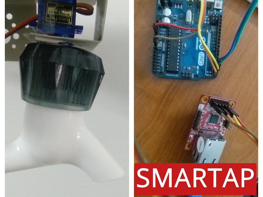
Smartap is a lightweight project that aims at automating the faucet. Main objective was to control minimise the water consumption. Wiznet WIZ750SR is the platform that has been used in the project along with Arduino Uno. Main steps to be followed are
- Configuring Wiznet WIZ750SR Serial to Ethernet module
- Setting up Arduino UNO
- Interfacing components
- Finalising
Usual taps I had at my house was old school. I wanted to add something extra to the existing components. Wiz750SR is a pretty good solution since it had easy RJ45 connector.
- Click controlled tap
- Flow control with relative to duration tap was pressed
- Control tap over network
- Determine waterflow rate and water consumed
- Set a threshold for the tap
- Leak Detection
Configure Wiznet WIZ750SR
The WIZ750SR is an ethernet to Serial convertor IC based on the Wiz7500mcu (ARM Cortex M0). It has a 10Mhz internal oscillator and 128kb flash memory. Most importantly the WIZ750SR works on the 3.3V logic. You have to first read the documentation to get a clear picture of the Wiznet IC.
To configure the Serial to Ethernet convertor, we can use the provided Wiznet configuration tool. First insert the WIZ750SR in the evaluation kit or connect the IC directly over the UART pins to PC.
Download the Wiznet configuration tool from the link: https://github.com/Wiznet/WIZnet-S2E-Tool-GUI
Then run the main_gui.py on your system (You should have python installed).
- On Windows machine, go to https://www.python.org/downloads/ and download latest version of python, then locate in cmd to the required directory and enter 'python main_GUI.py' and press enter.
- On Linux machine, go to terminal, locate to the required directory and enter 'python main_GUI.py' and press enter. Python will be probably installed on the machine.
This page should appear.
Connect the Wiznet evaluation board and press search. Select the device that shows up.
You can easily set the requirements of the device in here. For my project I setup in the following format:
- Operation mode: TCP server
- Local IP:192.168.4.1
- Local port: 80
- Baud rate: 115200
- Data bit: 8
- Parity: None
- Stop bit: 1
- Flow control: none
After setting all the preferences, click the settings tab. It will update the changes made and notifies with a confirmation dialogue box.
SettingupArduino
For this project, I used an arduino as it was easily available and easily interfaced with other devices. Any other micro-controller can be used as long as it supports UART communication.
Arduino can be set up pretty fast. Connect Arduino to the PC with the provided USB-A to USB-B connector. Check if the device is detected.
Startup the Arduino IDE which can be downloaded from https://www.arduino.cc/en/Main/Software.
Download the code that I have attached with this page below. Paste the code in arduino ide code editor and press the compile button on the top left corner.
Open tools menu>Boards>Arduino/Genuino UNO.
Open tools menu>port>"Select the port where arduino is attached".
Once this is done, press the upload button next to compile button. The uploading should complete without any error. You will have the Arduino successfully setup.
Interfacing Components
WaterflowSensor
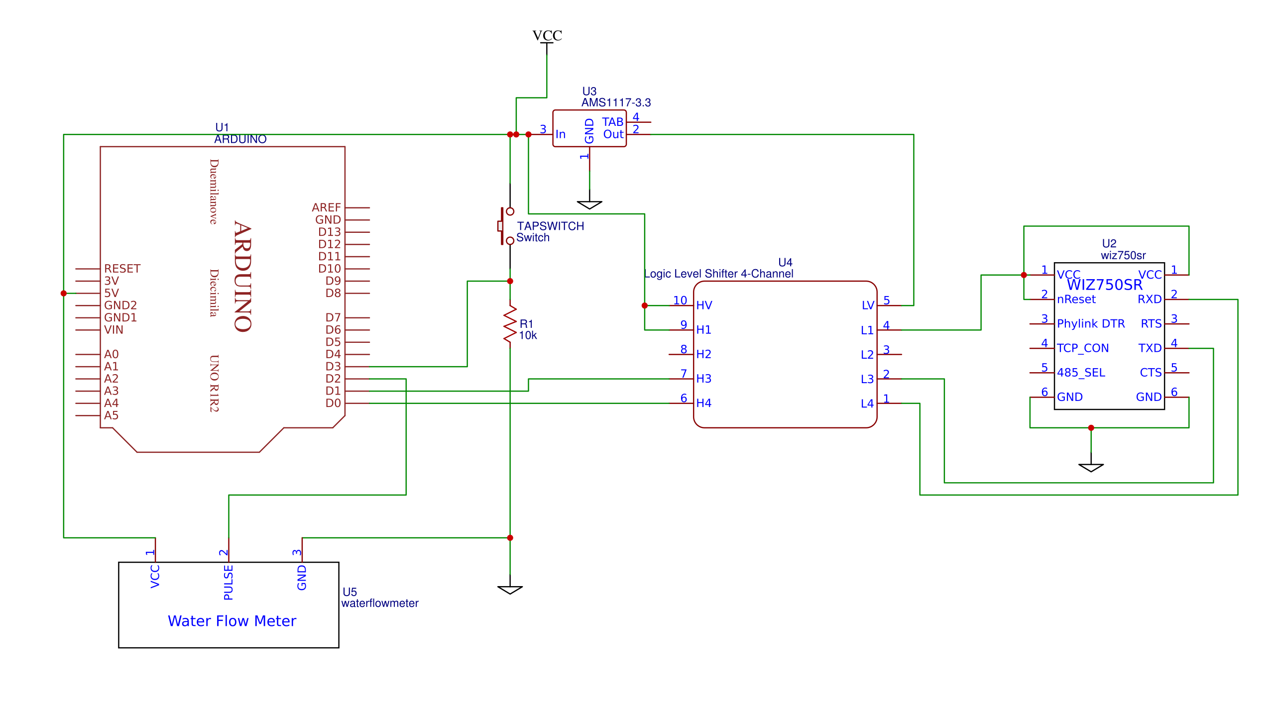
This sensor contains 3 wires- VCC, GND and Pulse. It has a small wheel with fins inside the casing. As one fin crosses the internal detector, a pulse is generated in the pulse pin. This is detected by the Arduino by assigning it as an hardware Interrupt pin. Refer the maincode.
- Connect VCC to 5v supply
- Connect GND to common ground
- Since pulse is interrupt controlled, connect it to pin 2
Tapswitch
For the tap control, we set up a small circuit as below.
Take the pin from data out and connect it to pin 3 of Arduino. Pin 3 is the second hardware interrupt of arduino uno.
Servo
You have to connect the servo to the tap to control it. Since I had a servo with less torque, I manipulated the tap a bit to easily control it with less torque. All that is required is to align the centre of the servo to centre of the tap rotation.
You have to choose the tap and control device appropriately. You have a choice of geared motor and Servo here. Since I used a 90 degree tap, I could use a servo. Otherwise you can use a geared motor. But you will have to include the L293D motor driver IC and manipulate the code a bit (tapfunc()).
WIZ750SR
This is the most trickiest part of the project. The Wiznet IC is a 3.3v logic device whereas arduino is a 5v device. If you choose a 3.3v arduino nano, then you can skip to direct connection stage.
First you have to generate 3.3v from existing 5v. For that lot of regulator ICs are available. But I have used an AMS1117-3.3 voltage regulator. This comes mostly in a SOT package.
Wiring of the IC is given in the complete circuit. We will get a regulated 3.3v DC voltage from pin 2 of this IC.
Thats not it. The RX, TX pins of the WIZ750SR also works under the 3.3v logic. You can easily get a logic convertor IC from online. One such IC is the Sparkfun logic convertor.
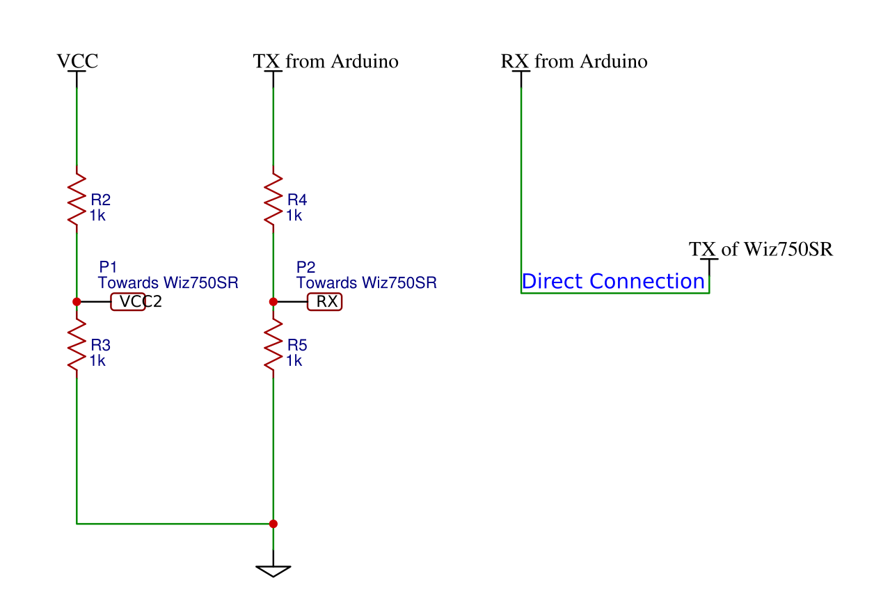
Alternatively, you can use potential dividers for the purpose also. But be careful when using the voltage dividers as logic convertor - deisgn the resistors ratio according to the equation
Vout = (R1/(R1+R2))xVin
As mentioned above, connect the RXD of S2E chip to TX of Arduino and TXD of S2E chip to RX of Arduino.
After this you will have successfully completed the interfacing and you must look messed up with wires.
The work is almost done.
Finalising
After all the connections are complete, turn the power On. You should see the Servo resetting to 0 position and all the power leds light up.
Open a browser on the connected network. Type in the ip address you had assigned to the WIZNET module. In this case - '192.168.4.1' and press enter.
You should be welcomed by a website looking like this:
You can remotely control the tap from this network - Turn it on or OFF.
If this part is complete, You have successfully completed the project. You can change the consumption threshold from the network webpage. Enter the data inside the text field and press the submit button.
Scope for developmentData from weather API can be downloaded. This data can be used to control the duration for which tap is turned on. The data can be uploaded to IOT services like Thingspeak or Ubidots and frequency of use of tap can be determined. Android app can be developed to use the Smartap.
Happy engineering!


_ztBMuBhMHo.jpg?auto=compress%2Cformat&w=48&h=48&fit=fill&bg=ffffff)


_3u05Tpwasz.png?auto=compress%2Cformat&w=40&h=40&fit=fillmax&bg=fff&dpr=2)
Comments
Please log in or sign up to comment.