


The Goddard Rover Prototype 1 is a core technology concept test to confirm Raspberry Pi 3A+ computers can be reliably used to create a functional remote controlled device. It proved to be a reliable platform to drive two 6V motors in a camera gimbal, two 6V motors in the wheel chassis, and two fans to cool the CPU and rig electronics. The operating system is Arch Linux ARM on all devices, communication is over standard Wi-Fi 2.4GHz transmissions (typical in homes and businesses), and have fail-safe recovery abilities should there be field interference.
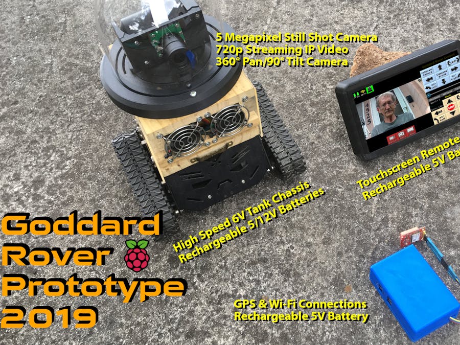
The streaming video is available on Wi-Fi using a fixed IP address that can be easily recorded on a local Wi-Fi receiving device such as a mobile phone, tablet, or other portable device, as well as LAN surveillance capturing systems. The Remote Control has a one minute record button that can be stopped if capture needed is shorter than a minute. Two other buttons allow a snapshot picture of the Rover camera video image or a snapshot capture of the Remote Control screen.
Rover Specifications:- Speed:.5 Miles Per Hour,.8 Kilometers Per Hour, smooth surfaces
- Average Battery Charge Life: 50 minutes, constant running.
- Remote Control Range Distance: Over 150 feet.
- Due to weight distribution factors, level surfaces are a limitation because the Rover can easily tip over mole and ant hills.
The Remote Control is a mobile touchscreen tablet with a graphical user interface created using Kivy graphical software components. The design for this user interface was to provide a test vehicle for this initial prototype. Other designs have been suggested that are much more mature but for this release, this provided the necessary functionality for concept testing for future designs.
The Remote Control screen shows the streaming video from the Rover with buttons surrounding the video image. The Rover navigation controls by default are on the right side, as illustrated in this screen capture below, but can be switched to the opposite side for left handed users. The top left shows the Rover (R) and Remote Control (RC) battery capacity levels, the Wi-Fi signal strength, and the Rover's connection status icons. At the bottom left side are the camera capture buttons to Record a 1 minute or less video capture, a Video Camera Snapshop, and a Remote Control screen capture button.
Camera Gimbal Remote ControlsThe Camera Gimbal sits on top of the Rover covered with a protective glass dome. It is a 3D printed parts kit assembled based on the instructions provided by hollerer, see references below. The Gimbal head mount holds the Arducam OV5647 5Megapixel camera to position the camera using pan and tilt controls. Inside the Gimbal housing, there are two DC Stepper Motors that are controlled by individual motor boards to make the pan/tilt movements using the 12V battery power.
On the Remote Control user interface, two programmed buttons turn the camera to predetermined Left and Right 90 degrees from the Camera Front position. Camera Front is calibrated using the left and right arrows to position the camera pointing forward on the Rover, then pressing the Calibrate Camera button.
Communications ModuleTo facilitate the Wi-Fi communications in fields away from all neighborhood signals, the Goddard Rover Communications Module provides the access point for both the Rover and the Remote Control. In addition, this module also includes a Global Positioning System (GPS) board at the end of the wire extension to set the date/time for all devices during startup. This same module will be used in the next prototype to track the Rover as it roams from one location to another.
In order to reconfigure both ends of the Rover Rig (camera top and electronics bottom), this design includes the ability to disconnect a few cables (fan and motors) to remove the core components from the chassis. As shown in the picture below, the Rover wheel chassis can sit next to the core electronic components.
Left in this picture is the wheel chassis with fan housing over the 12V battery shelf. To the right is the core electronic components that drive the wheels, pan and tilt the camera gimbal, and provides CPU its 5V power and the Motor board its 12V power, all from two batteries.
To develop and test the core electronic components and gimbal code, the rig can be set in its development docking station, as illustrated below. Based on the cylindrical design, the rig can be inserted either side up. This capability is essential for configuring and/or positioning each board in the stack and to route wires.
Camera/Gimbal side up allows changes to these components so that the internal gears and cable routes are in proper order.
Core Electronics side up allows location changes to each of the board, wiring, and spacing. This configuration also allows full device operation for tests, however without wheels and fans that are not connected. The Gimbal can be attached to the 12V battery for testing purposes.
Core Electronics ComponentsThe basic requirements for this prototype were as follows:
- Reliable CPUs, Power, Wi-Fi Communications, and Operating Systems for mobile Raspberry Pi Computers.
- All software is written in Python language to run all of the hardware components and use sockets to communicate between the Rover and the Remote Control.
- Basic system management with features such as cooling fans and power down safely before power outage.
- Ability to stack off-the-shelf (online purchased) boards with some level of support.
To accomplish these requirements, the first successful field tests, outside Wi-Fi neighborhoods, were configured as illustrated in the pictures below.


Comments
Please log in or sign up to comment.