


Hardware components | ||||||
 |
| × | 1 | |||
 |
| × | 1 | |||
 |
| × | 1 | |||
Software apps and online services | ||||||
| ||||||
| ||||||
| ||||||
TI not your thing? Check out my next generation bootloader and firmware update system stm32-secure-patching-bootloader.
IntroductionThe purpose of this demonstration is to show how a firmware update image can be securely hosted and retrieved from a publicly accessible cloud server and installed into the internal flash of a high-availability IoT MCU device. The device's internal flash is partitioned into 4 sections:
- A simple non-updatable bootloader in the BOOT section.
- A completely separate provisioning application containing features and functions intended only to be used during manufacturing of the device in the MTA section.
- Two equally sized executable application sections called APP1 and APP2.
There are two types of firmware image files used in this demo:
- The MAN image (short for manufacturing) is the combination of bootloader, MTA and APP binaries and is programmed onto the device's internal flash before it is sent to the field.
- The APP image is the main application implementing the device's main functions. The APP contains the OTA update logic, network stacks and/or interfaces and OS, and thus all components critical to the execution of the device are updated together. The APP is encrypted with AES-CBC. The APP can be placed into either the APP1 or APP2 sections at the discretion of the OTA update logic.
When the device is first provisioned with the MAN firmware image, the application image resides in the APP1 section, and APP2 is empty. The bootloader checks for a valid application in either section and boots the most recent (highest version).
The demo application polls a fixed URL for the presence of newer firmware images. When a new application image is found, it is downloaded through a TLS-secured link. The application image itself is decrypted on-the-fly with the MCU's embedded AES hardware and stored into the APP2 section. The update logic in this demo automatically and immediately reboots the device when the stored image has been verified. The bootloader then determines that the new image is valid and jumps to it, completing the update process.
If the update is interrupted at any time, for example mid-way during the download or during a flash write, or if the image could not otherwise be correctly written in its entirety to the APP2 section, the bootloader will not accept the content of APP2 and continue to boot the existing application. This is an extremely robust update process designed for IoT devices operating in real-world conditions and requires no external components. However, it comes at a cost - the amount of internal flash available to applications is reduced by half.
What will happen?- The firmware application running on the MSP432 target MCU will be updated by downloading a new version of the same application from a folder on GitHub.
- Every time the running application successfully connects to your local WiFi AP, it will send a tweet to https://twitter.com/MSPLaunchPad/ containing the "Unique ID" shown in the terminal window.
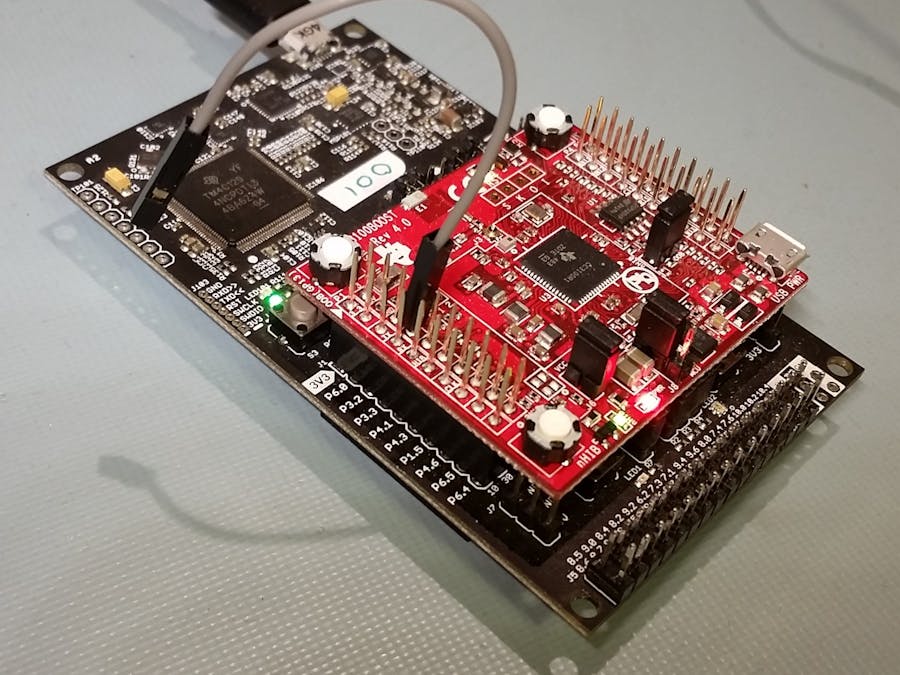
Assemble the hardware. Assemble the MSP432 LaunchPad and CC3100 BoosterPack as shown in the cover image and connect to your PC with a USB cable.
Get the firmware files. Download the firmware loader tool fm_load.exe and the OTA-MSP432-CC3100_x_x_x_MAN_x.bin firmware binary programming file to a folder on your PC.
Test the connection. Open a console and run fm_load.exe to ensure your LaunchPad is connected. You should see the following:
Firmware Module System Firmware Loader v1.1.56
Copyright (c) 2016 Firmware Modules Inc.
License: https://github.com/firmwaremodules/iotfirmware/blob/master/tools/LICENSE
INFO:root:Board unique id 0000
INFO:root:DAP JTAG MODE initialised
INFO:root:6 hardware breakpoints, 4 literal comparators
INFO:root:CPU core is Cortex-M4
INFO:root:FPU present
INFO:root:4 hardware watchpoints
No operation performed
Start the terminal. Start a terminal emulator session/connection on the LaunchPad's "Application/User UART" at 9600 baud. On some PCs, in Tera Term this appears as "COM4: XDS110 Class Application/User UART (COM4)". Choose the COM port that is assigned by your PC.
Load the firmware. Load the MAN firmware binary with fm_load OTA-MSP432_1_0_15_MAN_0x1509FB65.bin. Observe loading progress to completion (100%):
Firmware Module System Firmware Loader v1.1.56
Copyright (c) 2016 Firmware Modules Inc.
License: https://github.com/firmwaremodules/iotfirmware/blob/master/tools/LICENSE
INFO:root:Board unique id 0000
INFO:root:DAP JTAG MODE initialised
INFO:root:6 hardware breakpoints, 4 literal comparators
INFO:root:CPU core is Cortex-M4
INFO:root:FPU present
INFO:root:4 hardware watchpoints
[====================] 100%
Now observe the serial terminal window's output showing the need to set the WiFi parameters which we'll do next.
Provision the device's WiFi settings. To do this we must boot into the device's MTA (manufacturing test application) by pulling GPIO P4.0 high and resetting the board. Connect a short jumper wire as shown between the BoosterPack connector pins P3-4 and P1-1 and press the reset button.
The serial terminal will show a simple menu requesting that you fill in 3 fields, your WiFi network's SSID, security type, and passkey. Enter each in turn as shown.
When complete, commit the settings to flash with menu option 4) Save WiFi settings . Remove the jumper wire from the 3.3V pin but leave the other end attached - you'll need to use it again later.
Perform the update. Reset the board (ensure the jumper is disconnected) to boot back into the main application. This time it should connect to your local WiFi network and proceed to download and install the firmware update sourced from OTA-MSP432-CC3100_1_1_15_APP_0xA94C2B4C.fmu.
This update is identical in function to the previous version, except that the version 'minor' digit has been incremented from 0 to 1, and there is an extra message in the banner indicating that the updated app is running. When the update is complete, the board automatically reboots and you should see the updated application now running out of the internal flash's APP2 section.
Rollback the update. Re-connect the jumper wire between P4.0 and 3.3V and reset the board to access the MTA. The menu will have a new option 5) rollback a firmware update as shown. Select this option and confirm with y .
Interrupt the update. Remove the jumper wire again from the 3.3V pin and reset the board to boot the main APP. Now this time around, you want to have your finger hovering over the reset button as the demo progresses. When the updating......... text begins to appear in the terminal window, press the reset button to interrupt the download mid-update.
At this stage, a portion of the image has been written to the APP2 section in internal flash, and a flash write operation may have been ongoing. When the application boots up again, it remains untouched and is the same as before. The update is detected and re-attempted. You can also remove power to the LaunchPad during this update period. If you miss the update window and it completes, just perform a rollback again. See the example terminal window output below.
The bootloader, manufacturing test application and main application are independently developed, compiled and linked with complete vector tables. They are assembled into the combined MAN image in a post-build ("release") step. At the same time, the application images are embedded into a firmware update container format (.fmu) and then encrypted. You can confirm that the .fmu file is encrypted by noting that there is no evidence of a vector table anywhere in the file including the SP and PC initialization values typical at word offsets 0 and 1.
The bootloader is located at the beginning of the MAN image and after programming, it is placed at the location where the Cortex-M4 processor expects an application to reside on startup. The bootloader performs self-tests, checks the status of the MTA selection pin (P4.0) and verifies the integrity of all application images to decide where to set the processor's VTOR (vector table offset register). Once the VTOR is set, the PC (program counter) is moved to point to the target application's reset vector (specified at word offset 1 in the target application's vector table). The bootloader's job ends there and the application's startup procedures take over and reconfigures the device as required for the application.
If the bootloader encounters any fatal errors, it is designed to signal the error condition to port P1.0 - conveniently attached to the LaunchPad's red LED1.
The encryption key is stored with the application and is therefore vulnerable to inspection in the MAN image. However the MAN image is not distributed and intended to be used only in a "trusted" product manufacturing environment (such as your workbench or lab). Once the MAN image is programmed onto the device, and the JTAG port has been disabled and the MSP432's own INFO-section bootloader has been disabled or password protected, the encryption key and indeed the firmware content itself is no longer easily accessible to anyone that can gain access to your firmware update file or device.
What's nextYou've just experienced the result of significant behind-the-scenes effort to coordinate the production and consumption of multiple firmware entities for an MCU-based IoT device. This IoT firmware update demo is just the tip of the iceberg when it comes to the complex world of IoT device management. Other, more functional and perhaps interesting, IoT applications will be built on top of this technology.
This specific demo could be enhanced to show:
- Updating the firmware on the external CC3100 network processor using the same transfer mechanism. Instead of "APP" files the network processor updates could be "NWP" files and the OTA server running on the MSP432 would route those update file contents to the CC3100's SFLASH as appropriate.
- Provision the WiFi parameters using a mobile device.
- Pulling update files from other content distribution networks such as Sync or Dropbox.


Comments
Please log in or sign up to comment.