


Hardware components | ||||||
_ztBMuBhMHo.jpg?auto=compress%2Cformat&w=48&h=48&fit=fill&bg=ffffff) |
| × | 1 | |||
 |
| × | 1 | |||
 |
| × | 1 | |||
 |
| × | 1 | |||
 |
| × | 1 | |||
 |
| × | 1 | |||
 |
| × | 1 | |||
 |
| × | 1 | |||
Software apps and online services | ||||||
 |
| |||||
The "demand" I address with this work is reading the value of a resistor in a simple way to sort them back in the proper drawers and keep the table uncluttered. Yes, there's the color codes but... ;-( YES, there's the multimeter with the proper attachments but...
Is it not better to just plainly READ IT?
I started this first project as a way to learn better and make it available a great idea to those who have just started with a basic kit.
So I started this first project as a way to learn better and make it available a great idea (Federico's - see credits) to those who have just started with a basic kit and the UNO board.
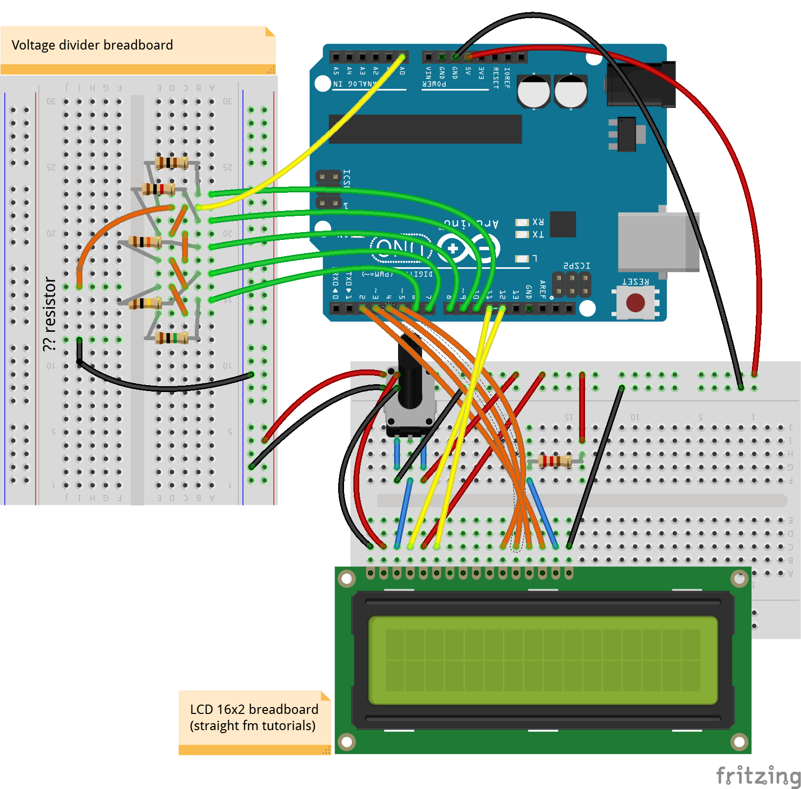
The theoretical principle that is applied here (and in many other projects) is the "Voltage divider equation" (see Wikipedia https://en.wikipedia.org/wiki/Voltage_divider) - to make difficult things simple it is a way to calculate one resistor value that you don't know putting two one after the other and reading how much of the total voltage the know resistor make you read at its terminals. The nearer the two are the more precise the result can be - so to make a balanced compromise we use five different values of know sample resistors.
Let's get started!!!
You need to make ready the components. The scheme below will easily take you to configure the breadboard. I used two different ones - to keep the 16x2 LED display function as much similar as to those of the tutorials (you should try the display as a separate part first, if you have not done it yet!) and get more visibility on the simple resistor part 'addition'. There's plenty of space left on the main breadboard to move it all on one - you just need to keep connected with the 5 green wires and the yellow one as before.
When you have arranged the components in this way you can also try to move it around checking with the schematics below:
At the end it should be something like...
Now is time to open up the coding - pick up the code in the proper section of this page and start reading it to feel it up. As everything in an Open Source environment it is a collage of what others have built before us. In particular all the sections that enable the visualization on the LCD is very standard.
I added on the original project a FUNCTION - that is a separate piece of code that gets AFTER the usual two sections of "setup" and "loop" - that can be "called" to make a specific calculation or - in the case a formatting - of one or more variables. I used it to transform a number 1.000.121, 34 in a string that is readable after the normal conventions for resistors - such as 1MOhm. The rounding and formatting would need a more extensive testing to check for all exceptions and anomalies... help me there.
String OhmFormattingFunction(float Input) {
//FS 20200223 v0 - Ohm values formatting function **
String Result;
if (Input < 80) {
valore = (String(round(Input)));
suffisso = " ";
}
....
I confess I kept some words inside the code in the Italian (Leonardo's!) language but it will take just a moment for you to replace them with... whatever idiom you were born to or in the English we all share. There are extensive debugging inserts in form of printed serial text to follow the procedure from the monitor.
IMPROVEMENT PATH:
- First of all you should make this yours by adapting it to your style and needs - correct the unavoidable mistakes and try to improve the calculations and/or the formatting letting us all know by commenting (much appreciated)
- I strongly suggest you buy a 0.96" OLED display and try it out - it is quite inexpensive and easy to implement (see Federico's project)
- Another way to get nearer to a finished "product" is to port it to a Nano Every - I found that the pins are the same etc. (this requires soldering and although it is not difficult, it implies a different level of involvement).


Comments
Please log in or sign up to comment.