

Hardware components | ||||||
 |
| × | 1 | |||
 |
| × | 1 | |||
| × | 1 | ||||
 |
| × | 1 | |||
 |
| × | 1 | |||
 |
| × | 1 | |||
| × | 1 | ||||
 |
| × | 1 | |||
 |
| × | 1 | |||
 |
| × | 3 | |||
 |
| × | 1 | |||
 |
| × | 1 | |||
 |
| × | 1 | |||
 |
| × | 4 | |||
 |
| × | 1 | |||
 |
| × | 1 | |||
 |
| × | 2 | |||
 |
| × | 4 | |||
Software apps and online services | ||||||
| ||||||
 |
| |||||
 |
| |||||
 |
| |||||
| ||||||
 |
| |||||
| ||||||
Hand tools and fabrication machines | ||||||
 |
| |||||
 |
| |||||
 |
| |||||
 |
| |||||
 |
| |||||
 |
| |||||
 |
| |||||
Our goal was to develop a doorbell that not only detects movement and sound, but also integrates biometric recognition, dashboard notification and local data storage on a Raspberry Pi. We used motion sensors, biometrics, a push button, an RGB LED, an ESP32 and an ESP32-CAM for Live Streaming, a buzzer and a power supply as main components to create a smart doorbell. We also used Node-RED to create an interactive dashboard that processes the data sent by the doorbell and stores this data in a local database on the Raspberry Pi. We chose to use MQTT and MQTTS over a Wi-Fi for communication between the doorbell and the Raspberry Pi, as this enables fast and efficient communication between the various components.
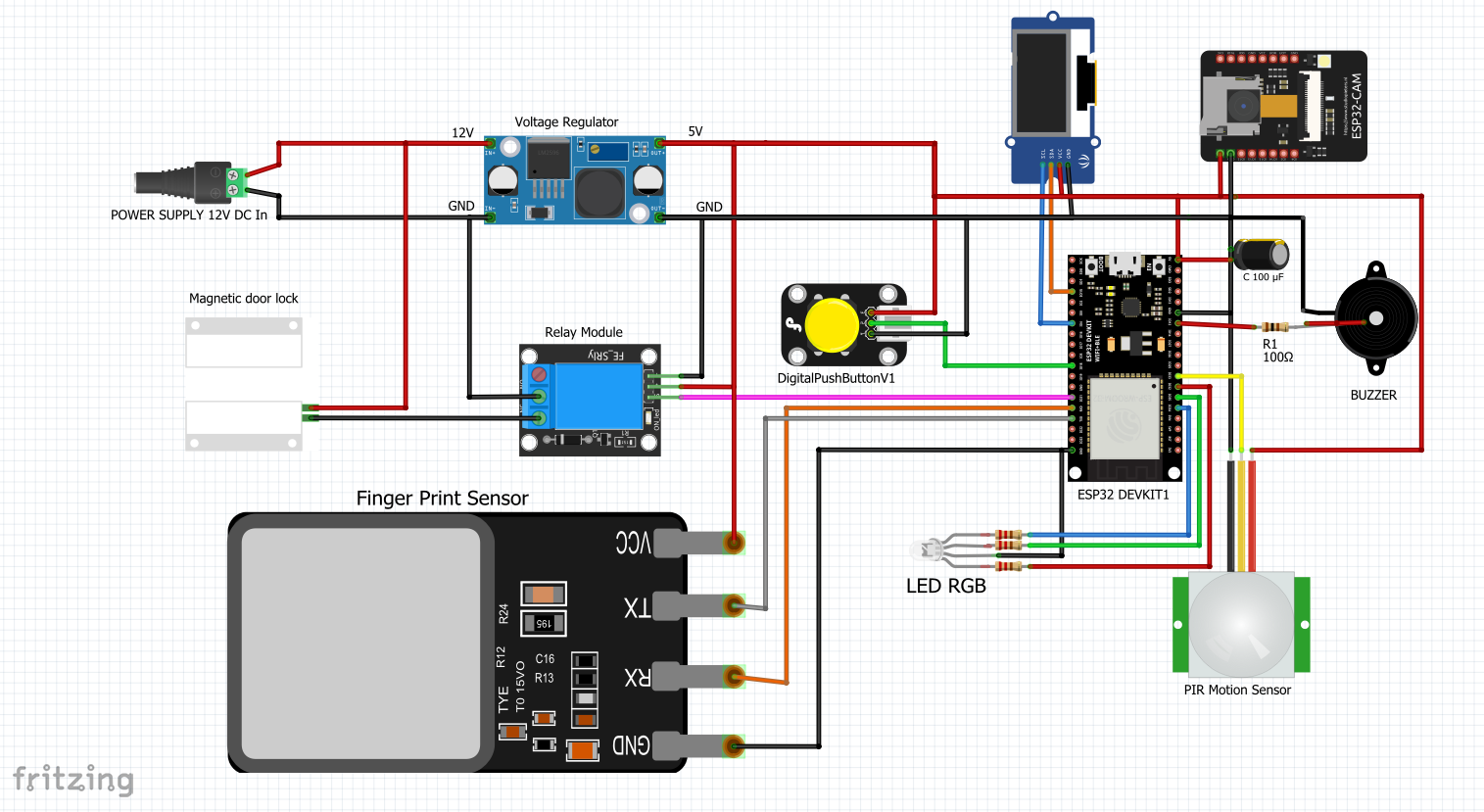
1. Components.To complete this project, we used many components, but the main ones are listed above. The circuit diagram summarizes the complete connection of the smart doorbell.
The components used are school materials for which I don't have reliable links. But here's the list with their purpose, type of connectivity and a description.
Our smart doorbell offers a range of advanced features to enhance the security and convenience of your home. Here are the main functionalities of our smart doorbell:
- Remote Door Control: With the mobile and web interface, you can remotely open and close your door. Whether you're inside your home or on the go, you can easily manage access with a simple tap.
- Voice Assistant Integration: Our smart doorbell is compatible with popular voice assistants such as Google Assistant and Amazon Alexa. You can conveniently manage doorbell functions using voice commands, providing a hands-free experience.
- Action Logging stored: Every interaction with the doorbell is logged and stored, allowing you to review the event history and track activities around your property.
- Live Video Monitoring: The doorbell is equipped with a built-in camera that enables real-time viewing of your doorstep. You can monitor your property from anywhere, anytime, using the mobile app or web interface.
- Biometric Door Control: Our doorbell supports biometric recognition, allowing you to unlock the door using your fingerprint. This provides added security and convenience for household members.
- Emergency Alert: In case of emergencies such as a break-in or suspicious activity, the doorbell can immediately alert the police or homeowners. This feature adds an extra layer of security for your home.
- Biometric Management via Interface: You can easily manage registered fingerprints through the user interface. Add new fingerprints, remove them, or update biometric information with just a few clicks.
- Motion detection : Our doorbell supports motion detection for use with anti-theft mode.
Those are the key features of my project, but I added more than that on the dashboard.
With these advanced features, our smart doorbell offers you complete control, enhanced security, and peace of mind for your home.
This project is a first version of a smart doorbell, and it's not made from high-quality materials, nor are they the best on the market.
3. Electronic DesignThe electronic design of our smart doorbell plays a crucial role in its functionality and seamless integration of various components. Let's take a closer look at how we designed the circuitry for our smart doorbell
There's the circuit diagram
- Microcontroller: We used an ESP32 as the main microcontroller for our smart doorbell. Its versatile capabilities, including Wi-Fi connectivity, powerful processing, and support for protocols like I2C, SPI, and UART, make it the ideal microcontroller for this project.
- Sensors: Our smart doorbell incorporates several sensors to enable its advanced features. We integrated a motion sensor (HC-SR501) to detect motion and trigger notifications. Additionally, a biometric sensor communicating via UART allows for fingerprint recognition, enhancing access control.
- Camera Module: The ESP32-CAM module with the OV2640 sensor is responsible for capturing and live streaming video from the doorbell. This module offers high-resolution imaging and seamless integration with our microcontroller. The microcontroller is solely dedicated to camera functionality and communicates with the Node-RED server via MQTT for synchronization with the doorbell and establishing a connection for live streaming through the local Wi-Fi network.
- User Interaction: We added a push-button and an OLED display to facilitate user interaction. The push-button allows visitors to ring the doorbell, while the OLED display provides visual feedback and prompts for biometric authentication and doorbell status.
- Connectivity: Our smart doorbell supports Wi-Fi connectivity, enabling smooth communication with the user's mobile device and the cloud. This allows remote access and control of the doorbell's features through the Node-RED Mobile App or the Node-RED Dashboard.
- Power Supply: To ensure reliable and consistent power, we integrated an LM2596 DC-DC converter. Our circuit (doorbell) is powered by a 12V supply with a current rating of 2A, also supporting the power requirements of the magnetic door lock.
- RGB LED Indicators: We integrated an RGB LED to provide visual indications of various states, such as doorbell activity, system status, authentication feedback, door opening and closing, and motion detection. The colors and patterns of the LED can be customized according to individual preferences.
- Our circuit also includes a capacitor to reduce noise in the circuit (voltage instability) caused by different components.
- Voltage Regulator: It reduces the 12V voltage supplied by the power supply to produce a usable 5V voltage for the microcontrollers.
The circuit design was carried out in two phases:
- Prototyping Phase: Component testing was initially conducted on prototyping boards to ensure the functionality of the project.
- Assembly Phase: Subsequently, all components were soldered onto circuit boards to be integrated into the doorbell.
By carefully designing and integrating these electronic components, we were able to create a robust and efficient circuit for our smart doorbell. This design ensures reliable operation and harmonious functionalities, providing an optimal user experience.
4. Writing CodeCode development for our project took place in two parts: the embedded part at microcontroller level (object side) and the server part (Raspberry Pi side).
Embedded part (object side):In the first part, the components were tested individually, then these codes were combined to obtain the final code taking into account all the functionalities. In the Github link, you'll see the various component test codes.
To program the microcontrollers, we used several development environments, including Arduino (IDE), Visual Studio Code (VSCode) and PlatformIO. This environment offers a user-friendly interface for writing, compiling and uploading code to the microcontrollers. It enabled us to program the specific functionalities of each component, such as sensor management, Wi-Fi and MQTT communication, biometric recognition and camera control. Arduino IDE and PlatformIO also provide feature-rich libraries that facilitate component development and integration.
Let us give you more details on the structure of the code. The github directory contains a hierarchy similar to the following:
The directory contains several folders. These include platformIO projects:
- ESP_FingerPrint: for testing the biometric sensor.
- ESP32CAM_SendMQTT: for testing the OV2640 camera while connecting to the MQTT broker on the Node RED server.
- ESP32_CAM: to test the operation of the ESP32-CAM OV2640 camera.
- ESP32_PushButton: to test the push button that will be used as a doorbell button with an ESP32.
- ESP_SPIFFS : to test the writing and reading of the ESP's ROM in order to integrate the server's configuration functionality into our doorbell.
- ESP_PIR: is the project for testing the motion sensor with the ESP32.
- TestingOLED: is the project for testing the OLED display.
- ESP32 - SmartDoorbell: this project contains all the doorbell's functions.
Server part (Raspberry Pi side):The Node-RED server plays a central role in our smart doorbell project. It is hosted on a Raspberry Pi connected to the local home network, and this is where the doorbell data is received, processed, and stored.
Node-RED is a visual development environment that allows us to create data flows using interconnected nodes. We used Node-RED to design an interactive dashboard that displays real-time information from our smart doorbell. Its intuitive interface enabled us to quickly configure nodes to communicate with the doorbell's microcontrollers using the MQTT/MQTTS protocol. Learn more here.
When the doorbell detects motion or someone rings the bell, the microcontrollers send relevant data as MQTT/MQTTS messages to the Node-RED server. The MQTT/MQTTS reception nodes on the server are configured to filter and process the received data, enabling real-time notifications to be displayed on the dashboard.
Additionally, we implemented nodes for managing biometric data. When someone attempts to open the door using biometric recognition, the fingerprint sensor sends the corresponding data to the server. The Node-RED server then performs a comparison with the previously registered authorized fingerprints in the local database. If there is a positive match, the door is unlocked.
As security is a major concern for our project, we implemented MQTT authentication to reinforce data exchange protection between the microcontrollers and the Node-RED server. Let's talk about the secure communication after.
Node-RED empowered us to design an intelligent and interactive doorbell management system. The dashboard displays real-time doorbell events, live camera images, and important notifications. Moreover, the doorbell data is stored in a local database on the Raspberry Pi, enabling the preservation of event history for further analysis.
With the Node-RED server at the core of our project, we have created a powerful and secure smart doorbell solution capable of seamlessly and efficiently meeting the needs of monitoring, access control, and visitor interaction.
My node-red dashboard (.json file) is available on GitHub here.
The Node-RED server is installed on a Raspberry Pi connected to the local network. It acts as a central platform for receiving MQTT/MQTTS data sent by the microcontrollers. Node-RED is a visual development environment for creating data flows using nodes. We used Node-RED to design an interactive dashboard that displays information from the smart doorbell. The data received is then stored in a local database located on the Raspberry Pi. This allows us to keep a history of doorbell events, and facilitate subsequent analysis.
The MQTT (Message Queuing Telemetry Transport) protocol is a lightweight, robust messaging protocol designed for IoT (Internet of Things) devices. It enables asynchronous communication between client devices, such as our smart doorbell, and a broker, which in our case is the Node-RED server. MQTT is well suited to devices with low computing power and limited bandwidth, making it an ideal choice for our embedded microcontrollers.
To enhance the security of MQTT communication, we opted for the MQTTS protocol, which is MQTT combined with SSL/TLS (Secure Sockets Layer/Transport Layer Security). This additional layer of security encrypts the data exchanged between our smart doorbell and the Node-RED broker, preventing any unauthorized interception of sensitive data.
In addition to the security provided by the MQTTS protocol, we have implemented MQTT authentication to further strengthen the security of our network. MQTT authentication requires every customer device, including our smart doorbell, to provide credentials (username and password) when connecting to the Node-RED broker. This ensures that only authorized devices can access and communicate with the Node-RED server, reinforcing the protection of our sensitive data.
In the knowledge that our MQTT broker is located in the same Ubuntu Server operating system located in our Raspberry Pi, but for a more correct understanding, I suggest you consider them as independent entities as they may not be in the same system.
To find out more about how to secure MQTT on Ubuntu, check out the following link:
By using the MQTT/MQTTS protocol and MQTT authentication, we've created a secure and efficient home network for our smart doorbell. This approach ensures that our doorbell data and interactions with the Node-RED server are secure and confidential, while maintaining smooth and reliable communication between the various system components.
By combining C/C++ programming languages for microcontrollers and tools such as VSCode, Arduino IDE PlatformIO and Node-RED, we were able to develop robust and functional code for our smart doorbell. This approach enabled us to take advantage of the advanced features of microcontrollers while ensuring seamless integration with the Raspberry Pi server.
6. 3D Design:The 3D design of our smart doorbell enclosure played a crucial role in ensuring a well-organized and functional integration of all the components. We carefully crafted the design to accommodate the electronic circuit, taking precise measurements to ensure a perfect fit. This section outlines our 3D design process, from modeling to the final product.
To create the 3D model of the doorbell enclosure, we utilized Tinkercad, an intuitive and user-friendly online 3D modeling platform. Tinkercad allowed us to design intricate shapes and structures by combining basic shapes and manipulating them to meet our specific requirements. Its simple drag-and-drop interface and extensive library of shapes made the design process smooth and efficient, even for those new to 3D modeling.
Once we had our design ready in Tinkercad, we exported the model and converted it into an OBJ file format, compatible with the 3D printer at our school. The OBJ file contained all the necessary specifications, ensuring that the printer would accurately reproduce our design.
With the 3D model prepared, we then used the school's 3D printer to bring our design to life. The 3D printer meticulously layered the material, gradually building the physical enclosure based on the digital model. We chose the appropriate material, such as PLA (Polylactic Acid), for its durability and ease of printing.
After printed, we got something like this :
The 3D design process, coupled with the capabilities of Tinkercad and our school's 3D printer, enabled us to realize a custom-designed enclosure tailored to our project's needs. The final 3D-printed enclosure not only protected the electronic circuit but also added a professional touch to our smart doorbell, making it a visually appealing and fully functional device.
The combination of 3D modeling and printing technology brought our concept to reality, showcasing the potential of 3D design in creating personalized and efficient enclosures for IoT projects like our smart doorbell.


_t9PF3orMPd.png?auto=compress%2Cformat&w=40&h=40&fit=fillmax&bg=fff&dpr=2)


_3u05Tpwasz.png?auto=compress%2Cformat&w=40&h=40&fit=fillmax&bg=fff&dpr=2)


Comments