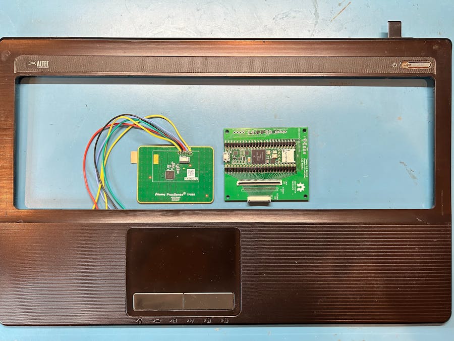
This touchpad project is a companion to my other Hackster project, titled "Laptop Keyboard Conversion to USB." The Teensy microcontroller is at the heart of these projects and it will help you repurpose your old broken laptop. I will focus on PS/2 touchpads but USB, Serial, ADB (Apple), I2C, or TTL are also used in laptops. Jump to the end for information on ADB and I2C interfaces plus raw strain gauge and Ergo Trac pointing devices. The Adafruit Trinket M0 is also shown.
All of the code described below can be downloaded from my GitHub repository by clicking the green "Code" download button on the right. Choose the Download ZIP option from the Code pull-down menu. The ZIP file will contain the entire repository content including the folder named "Example_Touchpads".
The challenge for making any touchpad work is determining the connections for ground, power, clock, and data. Synaptics touchpads often have round test points that are perfect for attaching wires. The typical test point numbers for a Synaptics PS/2 touchpad are:
- Clock = T10. If T10 is not present or doesn't work, try T12 or T5
- Data = T11. If T11 is not present or doesn't work, try T13, T9, or T6
- Ground = T23 or solder to the Ground Plane
- Power = T22. This test point provides an RC power filter. You can skip the power filter at T20 which feeds the power pins of the Synaptics chip .
This picture shows a touchpad with numbered test points. Some (but not all) Synaptics touchpads have a TM part number that includes a letter to designate the communication protocol. Some possible letters are: P = PS/2, A = ADB, T = TTL, and S = Serial. The touchpad shown below is PS/2 but the TM part number does not include any letters.
If your Synaptics touchpad has numbered test points but the PS/2 code doesn't work, it may use I2C or some other protocol.
The left and right "mouse" buttons are usually cabled to the touchpad board so their on/off status can be included in the serial data stream along with the X and Y movement. The picture above shows a 4 pin connector that is cabled to the buttons. The buttons could also be cabled directly to I/O pins on the Teensy.
Elan touchpads use a different test point numbering system as follows:
Clock = T7
Data = T8
Ground = TG0
Power = TV0
If your touchpad has no numbered test points, use all your Google skills to search for any information about your touchpad or the laptop's schematic. If you can't find any information or you are not sure it's accurate, use the following methods to determine the touchpad connections.
Ground:The picture below shows a typical touchpad. All signals are routed on the top layer and they use any leftover copper to make mini ground islands. The ground islands are all tied together to make a ground plane using resistors labeled 000. These zero ohm resistors are more cost effective to assemble than soldering jumper wires. Use your ohm meter to find the ground pin on the main connector that is tied to the ground plane.
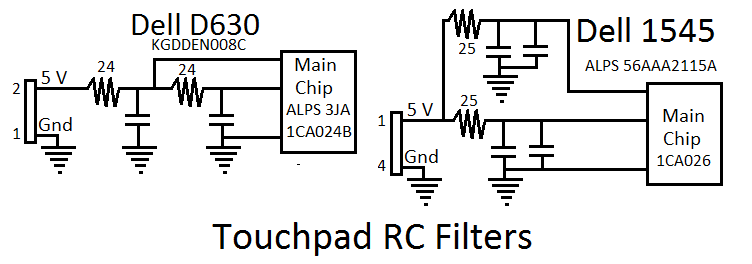
Newer touchpads are powered with 3.3 volts but 5 volts is more common for older laptops. The power from the main connector always goes to a wide trace that connects to a low value resistor. You can see the wide power trace in the previous 2 pictures and the picture below. The other side of the resistor goes to the main touchpad chip and to a capacitor. The resistor and capacitor make an RC filter to clean up the power for the main chip. Use your ohm meter to determine the power pin on the main connector that is tied to the RC filter.
The touchpad shown above only has power, ground, clock, and data pins on the main connector. To find which is clock and which is data, use the trial and error method described below. If there are too many possible signal pins on the connector to use the trial and error method, use the following procedure to weed out the obvious pins that can't be clock or data:
Only look at connector pins that are connected directly to the main touchpad chip. You are looking for 2 pins with very similar characteristics that behave like logic inputs. Measure and record the resistance for each pin to power and to ground. Next set your ohm meter to diode mode and connect the positive lead from your meter to ground. Use the negative lead to probe each of the possible clock and data pins in order to forward bias the ESD protection diodes. These pins (and any other logic signal pins) will read approximately 0.7 volts when an ESD diode is found. Sometimes the left/right buttons are wired to the connector directly. Switch your meter back to resistance and push the left and right touchpad buttons to see if the resistance changes so you can eliminate this pin. Put 3.3 volts across the touchpad power and ground pins (or 5 volts if you're certain this touchpad is a 5 volt device). Measure and record the voltage on each of the possible pins with a 10K pull down resistor to ground followed by the same resistor pulled up to power. This will show if the signal is being driven by the main touchpad chip and can be eliminated. Remove the resistors and push the left and right touchpad buttons to see if the pin voltage changes. Analyze the results of the resistance and voltage measurements to find the signals that act like logic inputs:
- Eliminate any pins that do not go directly to the main touchpad chip.
- Eliminate any pin that measures 2KΩ or less to power or to ground.
- Eliminate any pin that has a significant change in resistance or voltage when a button is pushed.
- Eliminate any pin that measures close to power when connected to a 10K pull down resistor.
- Eliminate any pin that measures close to ground when connected to a 10K pull up resistor.
- Group pins together that have similar measurements in order to test with the Teensy.
Hopefully you have reduced the number of possible clock and data signals and can use the trial and error method to find the correct 2 pin combination.
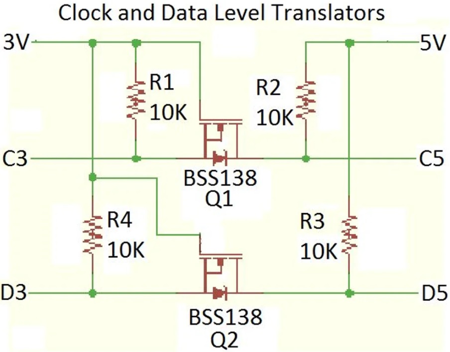
Trial and Error Method:Add a couple 10K pull up resistors to the two Teensy I/O pins that you will connect to the prospective clock and data pins on the touchpad connector. Once you get the touchpad working, try removing the resistors. You may find you don't need them because there are active pull ups in the touchpad chip. If you don't know the touchpad supply voltage, try 3.3 volts first. The Teensy 3.2 has 5 volt tolerant I/O and will work with 5 volt or 3.3 volt touchpads but it's obsolete and hard to find. The Teensy LC, 4.0, and 4.1 are not 5 volt tolerant so they need a level translator like the Adafruit 757 when connected to a 5 volt touchpad. My latest Teensy 4.0 and 4.1 connector boards described in my Instructable include pads for FETs and pull ups to make level translators so you don't need the Adafruit 757. Connect two of the Teensy I/O pins to the suspected clock and data connector pins. Download the touchpad code "Touchpad_Remote_mode.ino" from my repo into the Arduino IDE and edit the clock and data pins to match the I/O numbers wired to the touchpad. Under Tools, set the code to the Teensy model you are using and to "Keyboard+Mouse+Joystick". Compile and load the code into the Teensy.
Note that if you are using the Teensy 2.0++, it has 5 volt I/O signals that can directly drive a 5 volt touchpad. A 3.3 volt touchpad will need a level translator so it is not damaged by the 5 volt signals of a Teensy 2.0++.
My Arduino code bit-bangs two of the Teensy I/O pins to create a PS/2 clock and data bus per the Synaptics touchpad interface protocol given in documents 511-000275-01 and 510-000080-A. At power up, the code will try to initiate a self test and then read the result from the touchpad. If the bus is connected correctly, the touchpad will respond with "test passed" and the code will turn off the LED on the Teensy. Every 30msec, the touchpad will be polled for any movement or button pushes and the results will be translated by the Teensy to USB mouse commands that should move your cursor around.
If the clock and data are not correct, the Teensy LED will be turned on. Confirm no operation by swiping your finger across the touchpad. Swap the clock and data pins in the Teensy code, recompile and cycle power. If that doesn't work, move the jumpers to the next possible connector pins. Keep trying until every pin combination has been tested. If no success, add a level translator and increase the touchpad supply voltage to 5 volts so you can try all the pin combinations again. The level translator has its own pull up resistors so you won't need the 10K ohm resistors added previously.
Stream Mode vs Remote Mode:
The "Touchpad_Remote_mode.ino" code commands the PS/2 touchpad to be in remote mode so that it only responds with movement data when polled. This method fits in easily with a Teensy that is also scanning the keyboard matrix at a regular rate. Laptop motherboards don't use remote mode because the constant polling uses power. The low power approach is to initialize the touchpad to only send data when there is movement or button activity. The "Touchpad_Stream_mode.ino" code at my repo initializes the PS/2 touchpad to do this. This code is constantly looping, looking for touchpad data. If the Teensy is also scanning the keyboard, this code would need to be modified to execute when PS/2 bus activity causes an interrupt.
Connector Board:
Many touchpads interface to the motherboard with a small FPC cable so I created two simple connector boards shown below that can breakout the signals so you don't have to solder wires directly to the touchpad. One board will take a 0.5mm pitch FPC connector with up to 10 pins and the other will take a 1.0mm pitch FPC connector with up to 8 pins. The Eagle board files at my repo can be sent to OSH Park for fabrication. This board is also usable for breaking out the keyboard backlight signals so ignore the Drain, Gate, and GND pads when using it for a touchpad.
Some touchpads have a conductive cloth ground mesh that connects the backside ground to the palmrest (see Elan touchpad below). If you do not re-attach this ground mesh, the touchpad could give erratic cursor movement. To test a bare touchpad like this, you may need to press on the mesh with your finger.
The Apple Data Bus (ADB) is a single wire interface with a pull up resistor that runs on 5 volts. The interface is covered in chapter 5 of the Synaptics TouchPad Interfacing Guide 510-000080-A. Use the same methods described in the previous paragraphs to find the power, ground, and data connections to your ADB device. I used the ADB information and links described in this Imgur post to code a Teensy 3.2 that scans the keyboard and trackball of a Mackintosh Powerbook 140. The Powerbook code "ADB_Trackball.ino" can be downloaded from my repo. It will also work with a Teensy LC, 4.0, and 4.1 as long as you add a level translator to the Data signal. A Teensy 2.0++ will not need a translator.
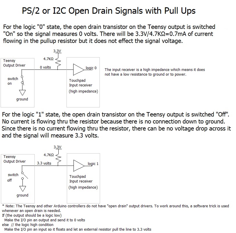
I2C:I2C touchpads are becoming more popular in modern laptops. This 2 wire clock and data bus can be directly driven by the I2C pins of a Teensy so no bit-banging is needed. Use the methods described in the previous paragraphs to find power (usually 3.3 volts), ground, clock, and data. There may also be a "Ready" signal that indicates when new data is available. This signal can be used as an interrupt or the Teensy can loop waiting for it to go active. The clock and data are open drain signals that require pull up resistors.
The touchpad's address can be found by hooking the clock and data to a Raspberry Pi 's I2C pins. Power the touchpad by connecting to the Pi's 3.3 volts and ground. The Pi already has 1.8K pull up resistors on the clock and data lines.
If you have not used I2C on this Pi before you will probably need to enable the bus and install the tools. Open the Raspberry Pi configuration tool by typing sudo raspi-config in the terminal window. Arrow to "Interface Options" -> "I2C" and select "Yes" to enable the interface. Reboot if prompted. To install the I2C tools, type sudo apt-get install i2c-tools in the terminal window.
To scan all I2C addresses and display which give an acknowledge, type the following in the terminal window.
i2cdetect –y 1
The -- address locations failed to give an acknowledge. Assuming you don't have any other I2C devices hooked to the bus, there will be one address that responds with an acknowledge and its address will be given (in hex). Use that address and dump all the register contents of the touchpad. An example for a touchpad at hex address 24 would be
i2cdump –y 1 0x24 b
This command reads all the registers in the touchpad and displays all the results in bytes. A basic touchpad will not have a lot of registers and they may end up repeating further down the list. Take note of the first 16 register values when the touchpad is idle. Next push and hold the left button and give the i2cdump command. Note which register changes and what value does it change to. Repeat this while holding down the right button. My example "simple" touchpad has the button values at register number 1. The left button gives a value of 0x03 when pushed and the right button gives 0x04.
Proceed with using the dump command while swiping your finger on the touchpad surface. My example touchpad has an 8 bit 2's complement value for the X delta movement at register 3. When you swipe left to right, this register gives positive values (the most significant bit is 0). Right to left movement has the most significant bit set, indicating a negative number. The Y delta values for my example touchpad are at register 4. Top to bottom finger movement gives positive values, bottom to top gives negative values. It is difficult to only move in X or in Y but after multiple attempts, you will narrow down which register has the X and Y values. Now that you know the I2C address and which registers to read, you can modify my simple Teensy code for your project. The code is given at my repo.
For a much more complex I2C touchpad with tons of features, try the Azoteq TPS65-201A-S available for $5.81 at Mouser. This touchpad has so many registers that it uses a 16 bit register address pointer. All of the registers are defined in the datasheet. The touchpad has the I2C pull up resistors built in so you don't need to add any. My Azoteq_TP Teensy code will work on any Teensy and is available at my repo. The touchpad has a 6 pin 0.5mm pitch FPC connector or you can solder jumper wires to the labeled pads shown below.
3V3 pad and GND pad to Teensy 3.3V and ground
SCL (Clock) pad to Teensy I/O 19
SDA (Data) pad to Teensy I/O 18
RDY (Ready) pad to Teensy I/O 10
RST (Reset) pad to Teensy I/O 12
Modern laptops sometimes have a multimode touchpad that will accept PS/2 clock and data signals on two connector pins or I2C clock and data signals on two other pins. If you just want the basic touchpad features, use the PS/2 pins. The I2C pins may use the Windows Precision Touchpad (PTP) protocol which provides numerous features not found in a basic touchpad.
Trackpoint/Pointing Stick:Thinkpad laptops often have an eraser head in the center of the keyboard called a "Trackpoint" that functions as a pointing device. Newer Thinkpad keyboards include a circuit on the back of the keyboard that converts the Trackpoint movement to PS/2 commands. The connections for a T61 are given below.
Notice that the trackpoint needs a positive reset signal at power up. I did a project that got the T61 keyboard, trackpoint, and touchpad working with a Teensy 4.0. The code, circuit board, and PDF files are at my repo. I did a similar project for a T41, also documented at my repo.
If your trackpoint/pointing stick does not output a serial bus, it may only provide the 4 signals from its strain gauge resistors. The motherboard circuitry detects the change in resistance and converts this to X and Y cursor movement.
The Dell D630 pointing stick has four 4K ohm strain gauge resistors that change resistance enough that the ADC in the Teensy can see the voltage changes above the noise. The Dell D630 pointing stick code and PDF are at my repo. Old Thinkpad trackpoints like the one on the 380 can also be converted to USB but its strain gauge resistors are only 350 ohms so the voltage needs to be amplified as documented in my Hackaday.IO project.
Fujitsu Ergo Trac Pointing Device:Some Fujitsu laptops have a pointing device called an Ergo Trac instead of a touchpad. This sensor uses magnetic field detection technology. The picture below shows the 4 connections that normally go to a controller chip on a CA20290-B40X daughterboard but it can also be driven by a Teensy.
The Teensy code at my repo drives a reference logic pulse to the sensor and reads the resulting pulse voltage with two ADC channels. The X and Y voltage is converted to USB mouse movements. The sensor part number is FID-828-100/20 and it can still be purchased on EBay and other sites.
I have installed the Ergo Trac in a project box along with a Teensy 4.1 that scans a Logitech K120 keyboard. The build has been described in the Hackster project here. The Teensy code is at my repo.
I have modified my Teensy PS2 and Azoteq I2C touchpad code for the Adafruit Trinket M0. The code and documentation is available at my repo. The picture below shows a 5 volt PS2 touchpad interfaced with a Trinket M0. An Adafruit 757 level shifter translates the 5 volt logic levels of the touchpad to 3.3 volts so the Trinket is not damaged.
I have modified my Teensy PS2 code for the Raspberry Pi Pico. The code and documentation is available at my repo.
This Synaptics touchpad has numbered test points that are connected to the Pico pins as shown below.
The Raspberry Pi Pico is not 5 volt tolerant so it needs a level translator if the touchpad is powered with 5 volt.
Next Steps:If you have successfully converted your touchpad to USB, the next step is to convert the keyboard. This is thoroughly documented in my Instructable titled "How to Make a USB Laptop Keyboard Controller".


Comments
Please log in or sign up to comment.