I purchased a few magnetic position sensors some time ago with the intention of using them in another interesting project. Due to lack of time and inspiration that project is still on hold. While cleaning up my desk the other day I saw the sensors and figured out I should at least try them out. I never tried anything similar before, so new learnings ahead!
Found a "problem" to solve!In a parallel universe there are a lot of people interested in puzzles of all conceivable kinds. One type of puzzle is the hidden cylindrical maze. There are many implementations of these, ranging from cheap 3D-printed (example) to exclusive machined metallic ones (like REVOMAZE). Due to the complexity of some of these puzzles the solver will need to go beyond memory and start mapping the puzzle. The mapping can be done in great many ways, most typically pen and paper together with measuring rotation and translation.
As a puzzle and maker geek I saw an excellent opportunity to build an automated mapping device!
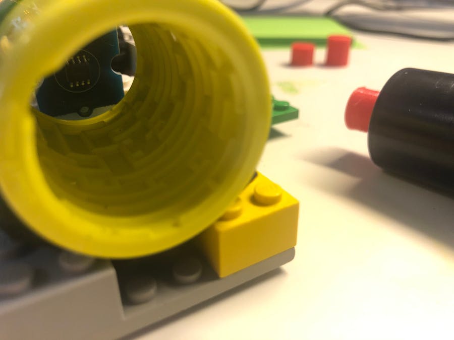
I started out with OpenSCAD and though I was going to make a nice 3D-printed holder for the puzzle and the magnetic encoders. It was fun for a little while, but then I got into the devil in the details when figuring out how to encode the translation of the shaft. Lego to the rescue! After a short excavation of the lego piles I found what I needed instead.
The CAD time was not completely in vain, I still needed small holders for magnets. You see, obviously the magnetic encoders need to have the magnetic field be perpendicular to the sensor. All small magnets I own are cylindrical and magnetized with North on one face and South on the other. 3D-printer to the rescue!
The Lego build was a simple ramp with a little sensor-car!
The 3D-printed magnet holders distance the 8mm magnet 1mm from the sensor when it is touching and this seems to work just fine. Now just put it all together:
Well, that was the whole build. Almost. There are of course a few more things to do...
The electronics & Arduino codeThe Magnetic Rotary Position Sensor uses I2C interface and is easy to interface with. Plenty of example code available on the internet. But, there was a but. To have to identical encoders connected I would need a I2C mulitiplexer as there is no way to change the address of them and the Arduino only has one I2C bus available. Bummer.
Since I own no such multiplexer I started looking at building one, but then I figured there must be a way to do I2C on regular GPIO pins? Yes, you can. SlowSoftI2CMaster to the rescue! 10 minutes later I was reading both sensors from the Arduino Uno.
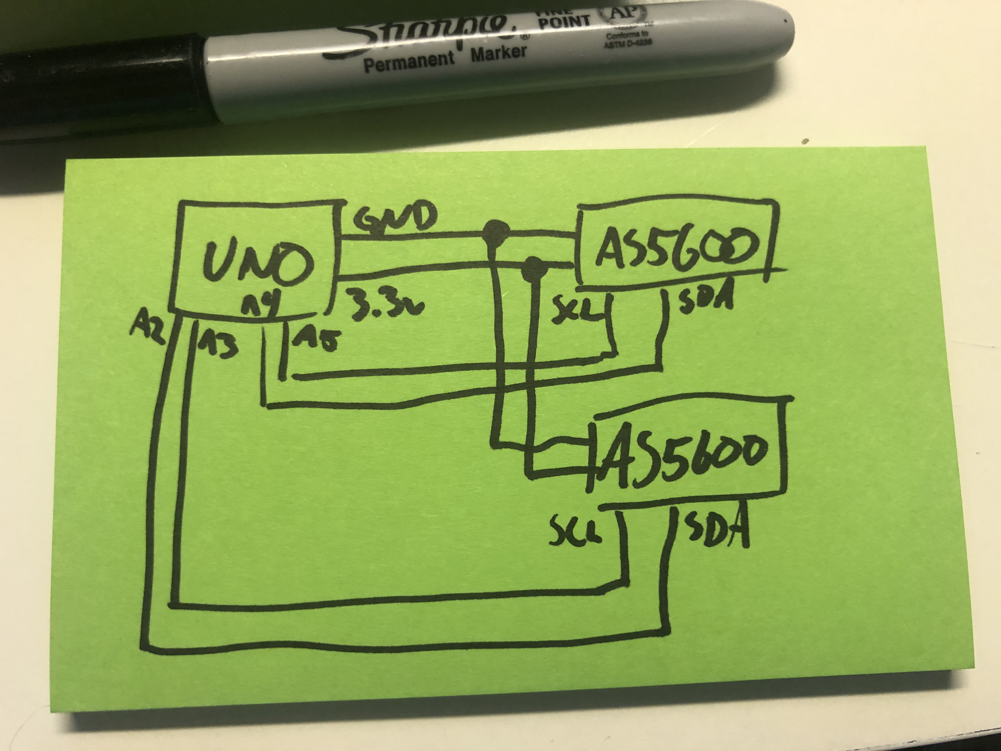
Electrical connection is too simple for a diagram. 3.3v and GND to both sensors, A2/A3 to one and A4/A5 to the second (picked the Ax pins just because the default I2C pins are A4/A5). Maybe there should be a pull-up resistor somewhere, but hey-it-works-tm. :-)
The code is on the Arduino is simple enough. Read the sensors, print on serial:
#include <SlowSoftI2CMaster.h>

SlowSoftI2CMaster si1 = SlowSoftI2CMaster(A4, A5, true);
SlowSoftI2CMaster si2 = SlowSoftI2CMaster(A2, A3, true);

#define I2C_7BITADDR 0x36 //AS5600

#define RAW_ANG_HI 0x0c
#define RAW_ANG_LO 0x0d

void setup(void) {
  Serial.begin(115200);

  if (!si1.i2c_init()) Serial.println("I2C init 1 failed");
  if (!si2.i2c_init()) Serial.println("I2C init 2 failed");
}

int readAngle(SlowSoftI2CMaster si) {
  if (!si.i2c_start((I2C_7BITADDR<<1)|I2C_WRITE)) {
      Serial.println("I2C device busy");
      delay(500);
      return -1;
  }

  si.i2c_write(RAW_ANG_HI);
  si.i2c_rep_start((I2C_7BITADDR<<1)|I2C_READ);
  byte val_hi = si.i2c_read(true);

  si.i2c_write(RAW_ANG_LO);
  si.i2c_rep_start((I2C_7BITADDR<<1)|I2C_READ);
  byte val_lo = si.i2c_read(true);

  si.i2c_stop();

  return val_hi<<8 | val_lo;
}

void loop(void){

  long val1 = readAngle(si1);
  long val2 = readAngle(si2);

  Serial.print("Sensor1=");
  Serial.print(val1);
  Serial.print("  Sensor2=");
  Serial.println(val2);

  delay(10);
}I made quite a hack of a visualisation software on my laptop. In short it works like this:
- Arduino outputs lines on serial port like "Sensor1=1234 Sensor2=456". Values are raw sensor values 0-4095.
- I read the serial data into a regular file by "sudo cu -l /dev/cu.usbmodem14101 -s 115200 > /tmp/cu_out.txt" (this works on MacOS)
- I have a Java program to which I pipe the file as input. The program takes each reading and converts into screen coordinates and paints the most recent reading in red and all historic readings in green.
- This program is so poorly written that I will save you all from the code. There is threading. I used AWT for the laughs. Coordinate system transformation is completely confused. Anyone with any coding experience should be able to write this better straight away or be able to learn to do so. I will not share this code. Sorry.
- The "Grove - 12-bit Magnetic Rotary Position Sensor / Encoder (AS5600)" is awesome!
- I2C is easy to use, but addressing of similar devices can be problematic. If you wanna I2C, get yourself a breakout board with a multiplexer!
- I learned how to read from the serial port on my Mac! One simple command and I had the data in a file ready to be consumed by any program written in any language. Zero complexity with weird serial port libraries etc. Debugging with "tail -f". Beautiful!


_ztBMuBhMHo.jpg?auto=compress%2Cformat&w=48&h=48&fit=fill&bg=ffffff)


Comments
Please log in or sign up to comment.