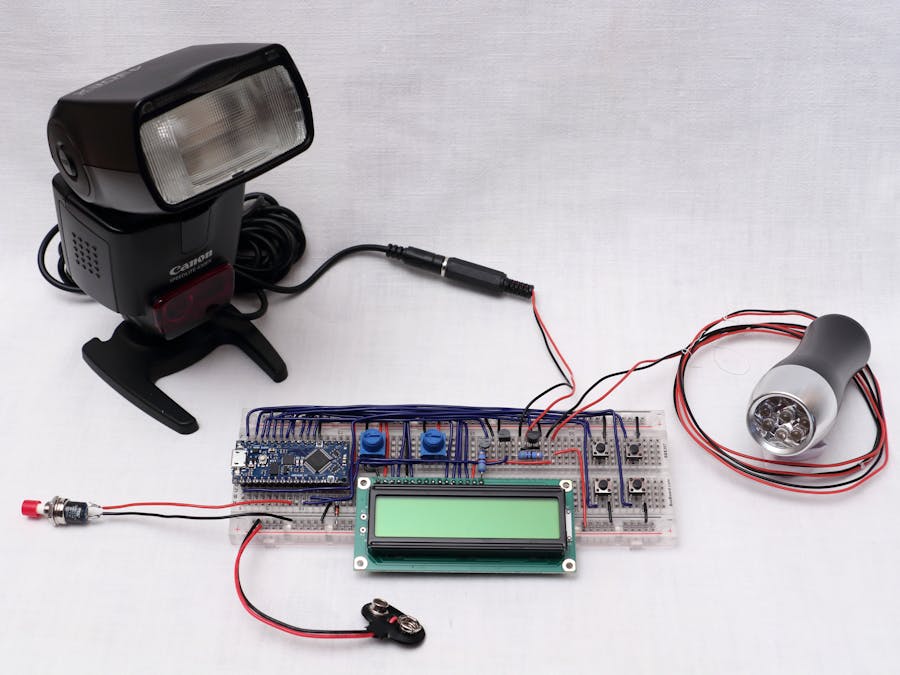
This stroboscope is said to be serious because it is not intended for fun or entertainment in the nightclubs. Rather it is a precise and versatile instrument which can be used to measure the rotation speed of a motor, or to analyze periodic movements such as that of a vibrating string. Optionally, it can be connected to an electronic flash in order to decompose and photography fast motions. Moreover, it can be synchronized on an external signal in order to convert it into a timing light, which can be used to set the ignition time of an old car engine.
It is designed around an Arduino Nano Every. The flashes are produced by a 9 LEDs ordinary torch whose 4.5 V battery has been replaced by two wires connected to the stroboscope circuit. The period and the duration of the flash can be set using four pushbuttons. Their values are displayed on a standard 16x2 characters liquid crystal display. They vary from 0.1 ms to 999.9 ms with a resolution of 0.1 ms.
The pushbuttons increase or decrease the flash period or duration at a speed increasing with the time during which the button has been pressed. This speed follows a law which can be changed easily in the code.
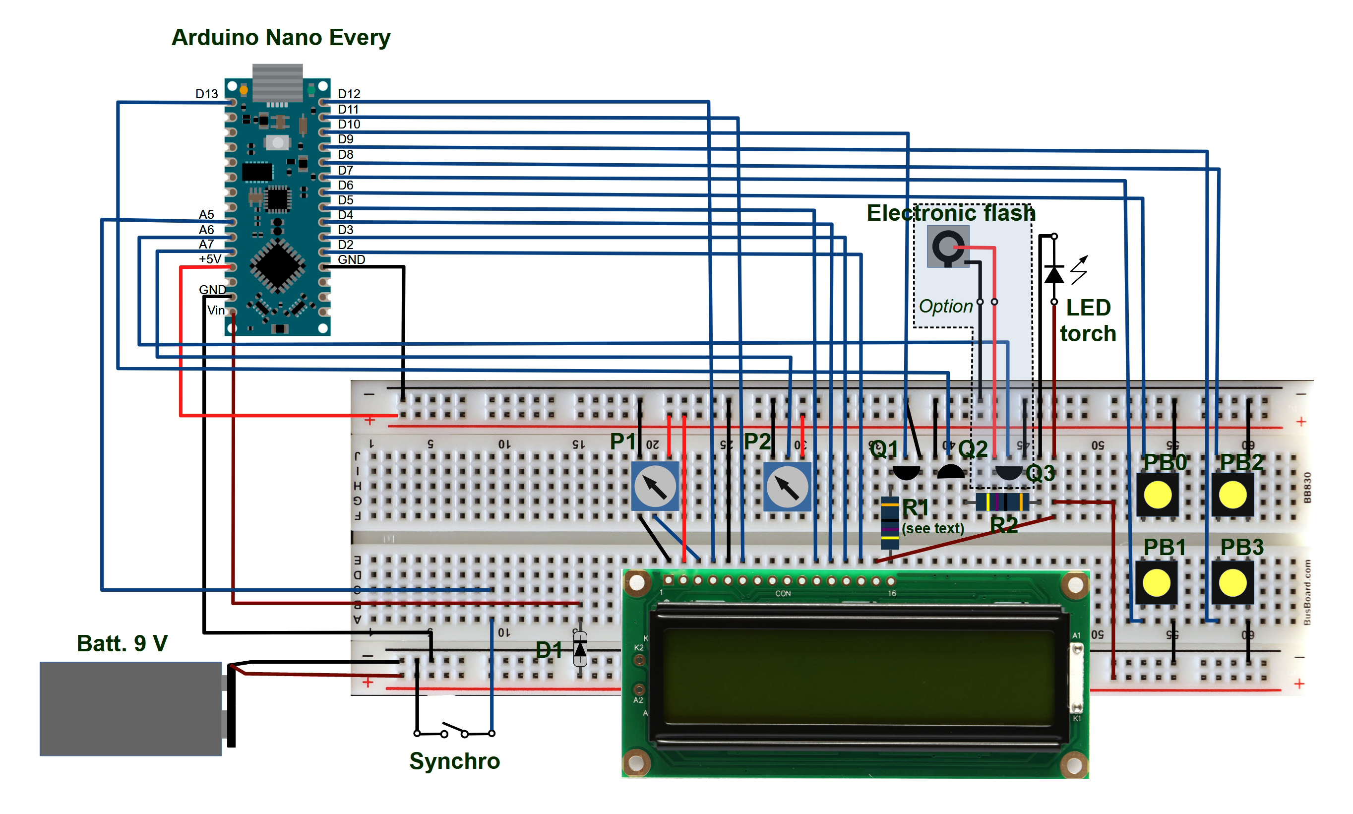
The LCD used to display the period and the duration is compatible with the liquidCrystal library and it is connected in the same way as in the examples of this library, except for the backlight which is adjustable by a potentiometer.
The stroboscope can drive an optional electronic flash by shortening briefly its central contact to the ground at each period. This flash can be used alternatively or simultaneously with the LED torch.
The synchronization of the stroboscope is obtained by shortening a digital input to the ground. When this input is grounded, the flash emission is stopped. When it is open again, the flash is emitted exactly one period later. Caution: when setting the ignition time of an engine, do not apply any voltage from the ignition system to the synchronization input, it could destroy the Arduino card.
Description and explanations9LED torch :
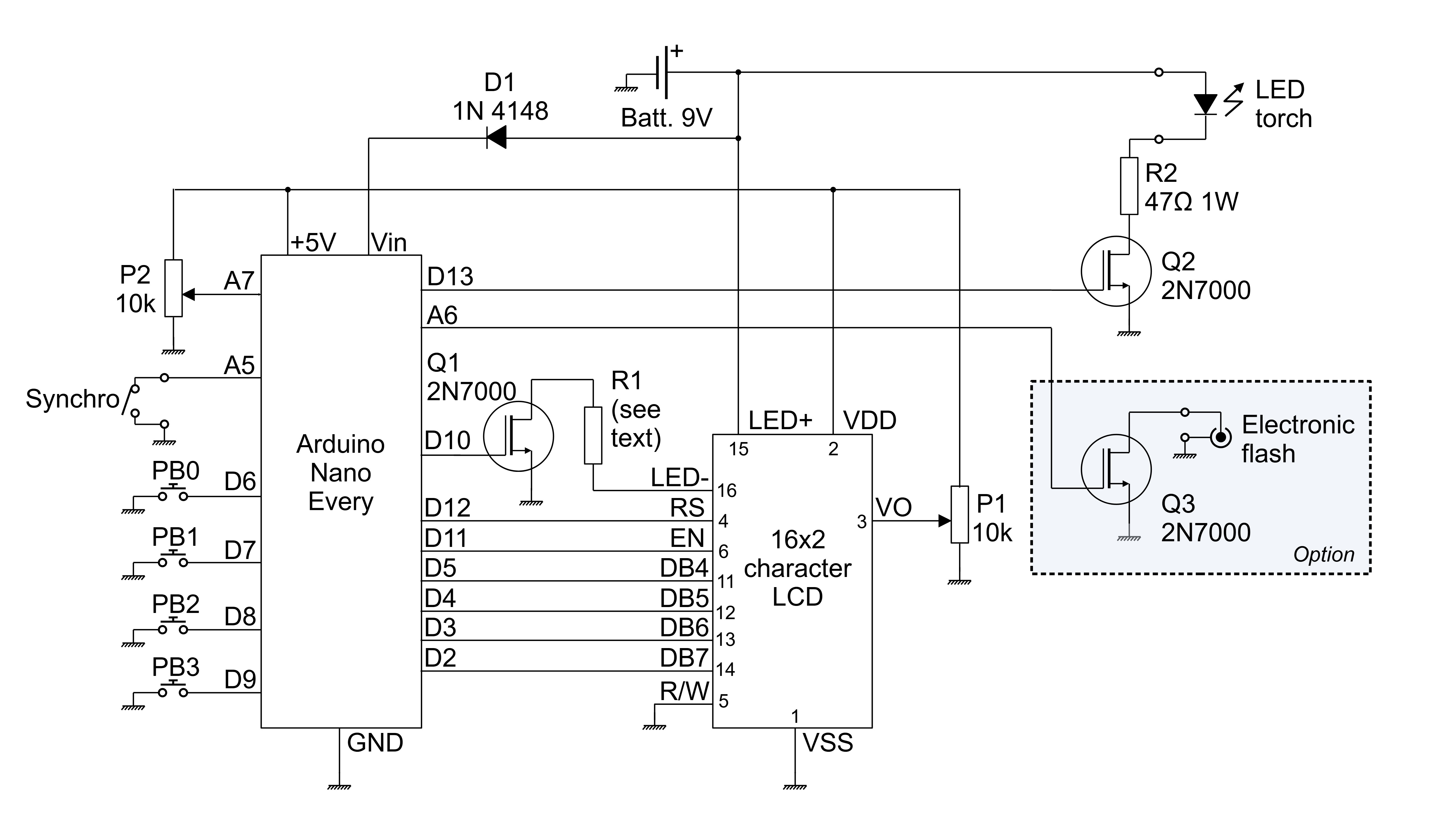
The LED torch is driven by the digital output D13 of the Nano Every. It is not connected directly to this output because it needs a current of 180 mA under 4.5 V and each ouput of the Arduino is limited to 40 mA. The torch is powered by the 9 V battery, through the N-channel MOSFET Q2 and the 47 ohms resistor R2. This resistor limits the current through the torch to about 100 mA which is sufficient to have a good light. The resistor must be able to dissipate a power of at least 47 x 0.1² = 0.47 W. A 1 W resistor is a good choice.
I have used a very ordinary torch with a 9 LEDs head to which I soldered two wires : the first one to the spring (anode) and the other one to the body (cathode).
Electronicflash :
The pin A6 of the Nano Every is programmed as a digital output which delivers a brief pulse at each period of the stroboscope. This output is connected to the gate of the N-channel MOSFET Q3. The drain of this transistor is open except while the pulse on pin A6 occurs, during which it is grounded. The central contact of an electronic flash may be connected to the drain of Q3 while its common is grounded.
This part of the project is optional for several reasons. First of all, you need to have an electronic flash (or buy it, but it is rather expansive). This flash must have a very short recycling time. Mine is a Canon Speedlite 430 EX. When I set it in manual mode with a power of 1/64th of the full power, and when its batteries are fully charged, I can set the period of the stroboscope down to 70 ms. You also need an adapter to connect the electronic flash to the stroboscope. I have got a Kaiser Fototechnik 1303 and a female 3.5 mm jack plug.
Pushbuttons:
The four pushbuttons PB0 to PB3 are connected respectively to pins D6, D7, D8 and D9 of the Nano Every. These pins are programmed as digital inputs with pullups and the pushbuttons connect them to ground when pressed.
LCD:
The LCD is connected in the same way as in the examples of the liquidCrystal library, it occupies the pins D2, D3, D4, D5, D11 and D12 of the Nano Every.
LCDbacklight :
The brightness of the LCD backlight can be adjusted by the potentiometer P2. This one applies a 0 - 5 V voltage to the analog input A7 of the Nano Every. The LCD backlight is driven by the PWM output D10 through the N-channel MOSFET Q1 and the resistor R1.
The LCDs are usually compatible with those using the Hitachi HD 44780 controller, but the world of their backlights seems to be a little more complex. I analyzed several LCDs, and I found that the voltage used to power their backlights varies from 3 to 5 V and the current varies from 10 to 130 mA. The proposed circuit (Q1 and R1) may be convenient for any backlight provided the resistor R1 is adapted as follows :
the value of R1 must be a little larger than (9 -Vs) / If, Vs being the voltage of the backlight, and If its current in A. The resistor R1 must be able to dissipate a power larger than (9 -Vs) x If.
Example : the backlight of my LCD needs a current of 130 mA under 4.2 V. So R1 must be a little larger than (9 - 4.2) / 0.130 = 36.9 ohms. I chose a 47 ohms resistor. It must be able to dissipate (9 - 4.2) x 0.130 = 0.62 W. In my case, R1 is a 47 ohms 1 W resistor.
Here are the LCDs I have analyzed :
Powersupply :
The stroboscope is powered by a 9 V battery. The Vin input of the NanoEvery is connected to the +9 V through the diode D1. Maybe some explanations are needed about this diode. When the Nano Every is powered by the USB, a voltage of approximately 4 V is present on the Vin pin. If the LCD backlight and/or the LED torch are connected to this pin, a current of 200 mA could potentially be drawn from Vin. The diode D1 protects the Nano Every by preventing any current from being drawn from Vin when the Nano Every is powered by the USB.
Synchro:
It is managed by just a few lines of code, and I simulated the signal with a pushbutton connected between the ground and the pin A5 of the Arduino, just to test this function.
ConclusionI hope you enjoy this project, and I think that two topics can be learned from it, besides having realized a stroboscope. The first one is the use of pushbuttons and an LCD to adjust a value of any type, following a law that can be adapted easily. The second topic is the adaptation to different types of LCD backlights and the ability of varying their brightness.


Comments
Please log in or sign up to comment.