


Hardware components | ||||||
_ztBMuBhMHo.jpg?auto=compress%2Cformat&w=48&h=48&fit=fill&bg=ffffff) |
| × | 1 | |||
| × | 1 | ||||
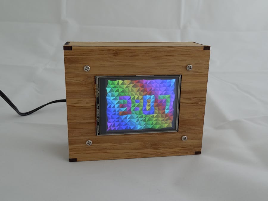
HSV Clock
When I visited the US last, I picked up a Seeed 2.8" TFT Touch Shield (V1.0) from a RadioShack. I used it to make a colourful clock for my father for his 80th birthday.
The important points are
- The clock face is based on a grid of rectangular cells. The cell corners are distorted by small random amounts and each cell is divided by a random diagonal. A random spread of colours is applied across the cells and each triangle is shaded to give a 3D look. Internally, the colours are represented as HSV (Hue, Saturation & Value) but converted to RGB for sending to the LCD. The time is displayed with a simple font by colouring certain cells in the complimentary colours.
- The enclosure is laser-cut bamboo, designed in Inkscape, cut by Ponoko.
- Unfortunately, the shield has no mounting holes so I effectively clamp it into the enclosure against the front face. An Arduino Uno piggybacks on the shield via the header pins.
- I needed I2C access to an external RTC (DS3232). The shield doesn’t expose unused pins so I used a Uno which has extra SDA/SCL pins. I made a low-profile header connector for these which sits under the shield. I pulled power and ground from a similar connector on the ICSP pins, also under the shield.
- I added simple Daylight Savings Time support to the sketch (one less clock to set twice a year!). Rather than deal with logic like “the last Sunday in September” it relies on a small table of specific start & end dates for future years (for New Zealand in my case).
- I simplified the Touch library code to make the touch screen just act as a 4x4 grid of de-bounced buttons. For example, the time is set by touching the bottom left and top right corners.
- I made some fairly heroic efforts to speed up the rendering: a repaint of the cells takes about a quarter of a second. The rendering is based around writing horizontal rows of pixels of a particular colour. I use a modified Bresenham algorithm to compute the horizontal extents of a series of pairs of lines which constitute triangles a given cell. The code which sends the pixels to the LCD is based on the library but in-lined, unrolled, simplified and optimised. Since pixel colour data is written across multiple PORTx’s, all the values are pre-computed when the colour is selected, so setting N pixels in a row to that colour is faster.
- The LCD is used in landscape orientation. I struggled for a long time to get the screen to update in horizontal rows. The datasheet for the controller is confusing. There are commands to set the “cursor” location, “DRAM Horizontal/Vertical Address Set (R20h, R21h)”. Pixel data is written at the cursor location and the cursor updates, wrapping onto the next line when needed etc. There’s also a command to change the screen orientation, “Entry Mode (R03h)”, which also talks about adjusting the cursor row and column increments. However, I found that changing the orientation to Landscape then positioning the cursor did not work. The solution I eventually found (which may be buried in the datasheet) is to use the “window” command instead of the cursor command; “Horizontal and Vertical RAM Address Position (R50h, R51h, R52h, R53h)”. Setting the coordinates of the top-left corner of the window means pixel data starts there and updates horizontally (in landscape).
Circuit
The circuit is simply
- the TFT shield mounted on the Uno.
- +5VDC, Ground, SDA & SDL go from the labelled pins on the Uno to the RTC module. Shown in the first three photos below (shield removed). Note that for access reasons, power/ground comes from the ICSP1 connector.

3 projects • 28 followers
Physics background, professional software developer, likes clocks


Comments
Please log in or sign up to comment.