


Hardware components | ||||||
| × | 1 | ||||
 |
| × | 1 | |||
Software apps and online services | ||||||
| ||||||
In today's industrial landscape, communication between devices plays a crucial role in automation and control systems. Modbus protocol stands out as one of the most widely used standards for this purpose. Leveraging the versatility of Raspberry Pi Pico W and the simplicity of MicroPython, we can seamlessly interact with Modbus slave devices. This guide will provide a detailed walkthrough of reading input register values from a Modbus slave device using Raspberry Pi Pico W, paired with a TTL to RS485 converter, all within the MicroPython environment.
PrerequisitesBefore delving into the tutorial, ensure you have the following components and prerequisites in place:
- Raspberry Pi Pico W.
- A Modbus slave device or Simulator (e.g., PLC, sensor).
- TTL to RS485 converter.
- MicroUSB cable for Pico.
- A computer with Thonny or another MicroPython IDE installed.
- Basic knowledge of Python and Modbus protocol.
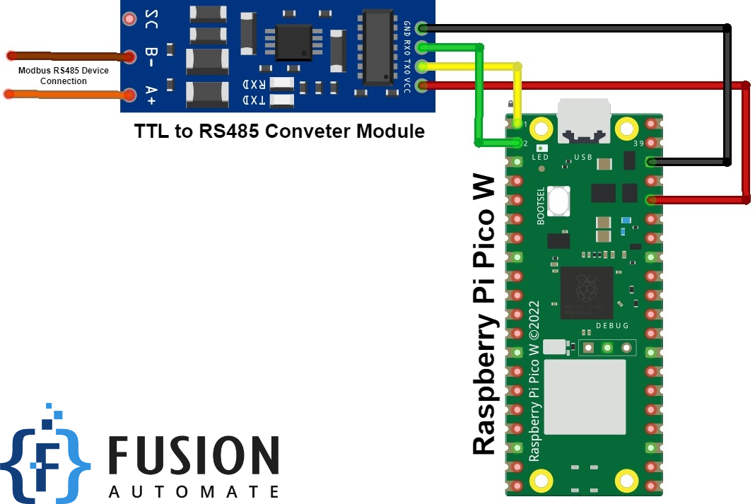
Setting up the hardware involves establishing connections between Raspberry Pi Pico W, TTL to RS485 converter, and the Modbus slave device:
- Establish connections between Pico's UART pins (TX, RX) and the corresponding pins on the converter.
- Connect the converter's A and B terminals to the RS485 lines of the Modbus slave device.
- Power up Raspberry Pi Pico W using a microUSB cable connected to your computer.
Before proceeding, we need to ensure the necessary libraries are installed for communication with the Modbus slave device:
- Open Thonny or your preferred MicroPython IDE.
- Install the '
micropython-modbus' library by following this guide [Watch]
Now, let's write the code to read input register values from the Modbus slave device:
import time
from machine import Pin, UART
from umodbus.serial import Serial as ModbusRTUMaster

# Define the pins for Modbus communication
rtu_pins = (Pin(0), Pin(1))

# Define the starting address to read from
starting_address = 0

# Define the quantity of registers to read
qty = 3

# Initialize Modbus RTU Master
host = ModbusRTUMaster(baudrate=9600, data_bits=8, stop_bits=1, parity=None, pins=rtu_pins, ctrl_pin=None, uart_id=0)

# Continuous reading loop
while True:
    try:
        print('INPUT REGISTER request test.')
        print('Reading qty={} from starting address {}:'.format(qty, starting_address))

        # Read input registers from the slave device
        values = host.read_input_registers(slave_addr=1, starting_addr=starting_address, register_qty=qty, signed=False)

        # Print the result
        print('Result: {}'.format(values))

    except Exception as e:
        print('An error occurred:', e)

    # Wait for 5 seconds before the next reading
time.sleep(5)To ensure that our setup is functioning correctly, we can perform a simple test:
- Connect Raspberry Pi Pico W to the Modbus slave device via the TTL to RS485 converter
- Run the script on Raspberry Pi Pico W.
Verify that the input register values are correctly read and displayed on the console output.
- Verify that the input register values are correctly read and displayed on the console output.
- Optionally, perform additional tests by modifying the script to read different input registers or quantities of registers.
In this comprehensive guide, we've explored how to utilize Raspberry Pi Pico W and MicroPython to communicate with Modbus slave devices using a TTL to RS485 converter. By following the steps outlined above, you can seamlessly read input register values from Modbus devices, empowering you to integrate Raspberry Pi Pico W into industrial automation and control systems with ease. Experiment, explore, and innovate with this powerful combination of hardware and software!

Comments
Please log in or sign up to comment.