


Hardware components | ||||||
 |
| × | 1 | |||
 |
| × | 1 | |||
 |
| × | 1 | |||
 |
| × | 1 | |||
 |
| × | 1 | |||
Software apps and online services | ||||||
 |
| |||||
In this article, I'll show you how to make it fade using the PWM capability of the ESP32.
If you are not familiar with PWM, please checkout Arduino Step by Step Getting Started.
The Arduino, of course, can also output PWM. But as you'll see, the ESP32 has got several additional capabilities in its hardware that the Arduino Uno with the Atmega328 cannot even imagine.
You can watch the video, or, if you are the "reading" type, you can read the text below.
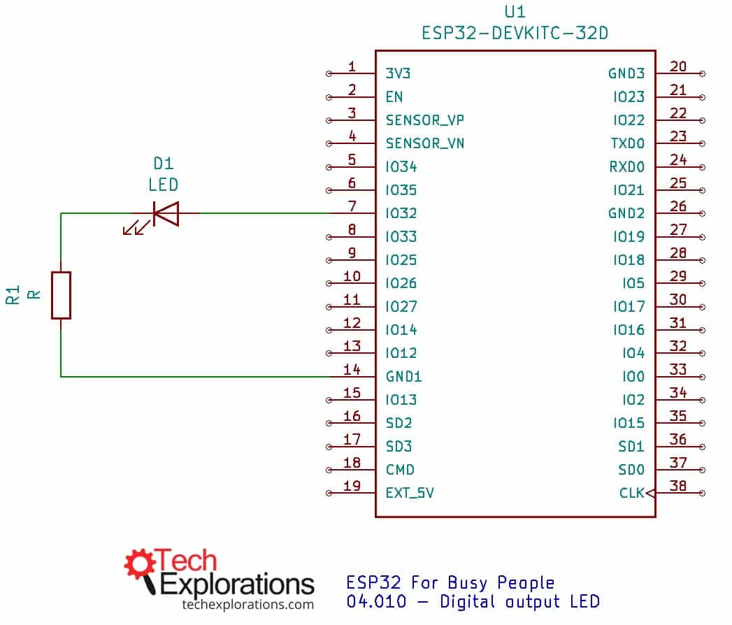
The wiringFor this experiment you can reuse the circuit from the previous lesson.
The circuit contains a single LED connected in series to a 230 Ω resistor. You can use any resistor value between 230 Ω and 500 Ω, and the LED will be bright.
Connected the anode of the LED to GPIO32 on the ESP32, and the cathode to the blue rail on the breadboard, which is connected to one of the GND pins of the ESP32 dev kit.
You can see the schematic below.
An LED is controlled by GPIO32, and is protected by a 230 Ω resistor connected to GND1.
I have connected my LED to GPIO32, though I could have used any of the other pins (with some exceptions that I'm going to discuss about later).
GPIO32, as most other GPIOs, are PWM-capable.
The sketchHere, I think it is useful to compare the Arduino version of the fading LED sketch, with the ESP version. I have them side-by-side below:
Arduino version
ESP32 version
In the Arduino, we use the analogWrite() function to "write" a value between 0 and 254 to the LED pin. Larger values will cause the LED to stay on for longer during a cycle, and thus the LED will be brighter.
The analogWrite() function accepts two parameters:
- The number of the pin to which the LED is connected.
- The PWM value from 0 to 254.
Inside the loop function, each time it is called, the brightness value is increased or decreased by 5, depending on whether we are increasing or decreasing the LED brightness.
Simple.
The ESP32 does not support the analogWrite() function. But is does support a much better one, the ledcWrite() function.
The ledcWrite() is very similar to analogWrite(). It also requires two parameters:
- The PWM channel that we want to "write" a value to.
- The PWM value we want to write to the selected channel.
This simple function shows off the power of the ESP32. Both the channel and the PWM values are configurable.
The PWM channel is not the same as a physical pin. The ESP32 contains 16 independent channels. Each of those can be assigned to any PWM-capable pin. This means that you can use any 16 GPIOs to generate PWM output.
The resolution of the PWM signal is also configurable. While in the Arduino, an PWM signal is set to 8 bit, in the ESP32 it can be whatever you choose, from 1 to 16 bits.
To assign a PWM channel to a pin, and configure the resolution of the signal, the ESP32-Arduino Core software provides two functions:
ledcAttachPin(gpio, channel)ledcSetup(channel, frequency, resolution)
In ledcAttachPin(), pass the GPIO number and the channel number that you want to bind. In the example sketch, you can see:
ledcAttachPin(led_gpio, 0);This binds PWM channel "0" to GPIO32.
We use ledcSetup(channel, frequency, resolution) to configure the PWM signal. In the example sketch, you can see:
ledcSetup(0, 4000, 8)The first parameter is "0". This means that we are configuring PWM channel "0".
The second parameter is 4000, which means that we have chosen the PWM frequency to be 4KHz. The frequency range depends on the resolution you have chosen, but typical values for an 8-bit resolution are from 4KHz to 8KHz. If you are curious about the details, read this.
The third parameter is "8", meaning 8 bits. You can set the resolution to any value between 1 and 16 bits.
Use ledcAttachPin() and ledcSetup() function in setup() to... setup the PWM channel 0, and then you are ready to start creating PWM output.
Inside the ESP32 version of the sketch, have a look at the loop(). Apart from the substitution of analogWrite() with ledcWrite() , the code should look very familiar.
PWM signal visualization with the oscilloscopeThe ESP32 PWM output is very configurable, and this help in creating very precise output. I used my oscilloscope to see the PWM signal the was generated by my ESP32. It looks like this:
My oscilloscope visualises the ESP32 8-bit, 4KHz PWM output.
Please watch the video at the top of this article for the details of my experimentation with my ESP32 and the oscilloscope.
This concludes this introductory series on the ESP32. There's a lot more to learn.
If you are keen to make the most of your ESP32, consider enrolling to my full video course, "ESP32 For Busy People". Unless you have time to waste 🙂
Checkout our comprehensive resources on the ESP32This guide is part of our comprehensive set of free resources and video courses on the ESP32.
With these resources, you will learn how to use the ESP32 through a series of experiments. We'll start with the basics, like how to use the ESP32 to blink an LED, and work our way to more elaborate topics, like using its built-in sensors and communications capabilities.

Comments
Please log in or sign up to comment.