This robot has been a dream of mine for a while now, and it's finally done!
Features:
- Records video for a adjustable amount of time
- Streams video to a browser window
- Super small size
- Ultrasonic sensor controlled - fully independent
- All-terrain design
- Raspberry Pi Zero W - here at Adafruit
- Arduino Nano - here at Newark
- TT Gearbox Motor - here at Adafruit
- Super small Cardboard Box
- Male/Female Jumper Wires - here at Newark
- Female/Female Jumper Wires - here at Newark
- Male/Male Jumper Wires - here at - you guessed it - Newark
- DRV8833 Motor Driver - here at Adafruit
- Raspberry Pi Camera Module - here at Newark
- Slide Switch - here at Newark
- 9V Battery
- 9V Battery Clip - here at Newark again
- USB Li-Ion Battery Charger - here at Adafruit
- 2 Li-Ion Batteries 1000mAh - here at Newark
- Caster Wheel - here at Adafruit
- Raspberry Pi Zero to Camera Adapter Ribbon Cable - here at Adafruit
- USB to Micro-B Cable - here at Ebay
Apps:
- Raspberry Pi OS - here at Raspberry Pi
- Arduino Create Web Editor - here at Arduino
Tools:
- Rotary Tool - here at Dremel
- 3D Printer - here at Amazon - I have an Ender 3, and it's awesome - #notsponsored
This is where the 3D Printer comes in. If you want, you can print a chassis base for your box.
First, get out your hot glue gun and heat that up. (Don't worry, the hot glue is only temporary.) After it is heated, get whatever you used for a chassis base and glue the TT motors on it. Then, glue the box on top.
Step 2: Battery MountingUse a double sided adhesive tab and secure the 9v battery on the side, and use another to secure the 3.7v battery on the side. Put 2 normal jumper wires in the 3.7v battery holes. Put 2 M-F jumpers on the 9v battery wires. Drill a hole in the side of the box and put the 3.7v battery wires through.
The 3.7v battery is for the Arduino, and the 9v battery is for the motors.
Step 3: Motor Driver MountingCut a DRV8833-sized hole in the box with your rotary tool. (I advise you to measure it.)
Hot glue the DRV8833 in around the edges. I said hot glue because you might need to make changes.
Step 4: Sensor MountingTake your HC-SR04 and measure it. Get the length and width, then draw lines of the corresponding distance on the chassis enclosure, to make a cutting template.
Cut on the lines with your rotary tool.
Put the ultrasonic sensor through the hole. If it fits, great! If it doesn't, adjust accordingly. Make sure the "beams" are not obstructed.
Glue around it like you did with the DRV8833.
Step 5: WiringThis is the hardest part.
Because there are so many wires, I didn't make a circuit diagram, but the list below shows the pin numbers.
Pin Numbers:
- Trig of your HC-SR04 to pin 9
- Echo of your HC-SR04 to pin 10
DRV8833 Pins:
- AIN1 to pin 4
- AIN2 to pin 5
- SLP to 3.3 V
- BIN2 to pin 6
- BIN1 to pin 7
- AOUT 1 to Left Motor RED
- AOUT 2 to Left Motor BLACK
- BOUT 2 to Right Motor BLACK
- BOUT 1 to Right Motor RED
Put the power wires to their respective places, as always. I recommend breaking out each power pin to a breadboard strip. Put the Nano in the box (you can't wire it if you don't).
Plug the red of the 1st battery into the VIN of the Nano, then when you are ready to roll, put the black of the battery into GND.
Step 6: CodingDownload the code for your Arduino here at GitHub. Upload it to your Nano.
Run the .py file on your Raspi Zero on boot like this:
Run this command in Terminal :
sudo nano /etc/rc.localAdd this line right before the exit0 line:
python3 /home/pi/Desktop/(Ra)Spy-Bot Cam.py &Press ctrl + x, then y, then enter.
That's it!
For streaming, do the same thing, but add this line right before the exit0 line:
python3 /home/pi/Desktop/(Ra)Spy-Bot Stream.py &Note: Change the file names and paths to what they are for you, for example:
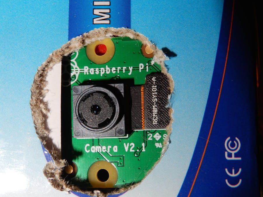
python3 /home/pi/Documents/your_file_name &Drill a hole through the front big enough for your camera, then put your camera with the adapter cable into your Raspi Zero's connector.
Put the camera through the hole, then glue the edges. Put your Zero in the chassis enclosure. Put the USB to battery converter in your box, then when ready, plug er' in and watch it record!
Step 8: Done!Make sure nothing is shorted in the enclosure. Turn it on. If it works, congratulations!!! You did it!
Do a test mission to celebrate, then kick back and watch your 1 1/2 minute show or stream!
Thank you for viewing my project!
Until next time,
Merry Making from g3holliday


Comments
Please log in or sign up to comment.