

Hardware components | ||||||
_ztBMuBhMHo.jpg?auto=compress%2Cformat&w=48&h=48&fit=fill&bg=ffffff) |
| × | 1 | |||
 |
| × | 1 | |||
Software apps and online services | ||||||
| ||||||
Hello!
Today I’m posting an example project using one of CapSense MBR (Mechanical Button Replacement) development kits, the CY3280-MBR3 CapSense evaluation kit. The CapSense device on the kit uses register configuration to enable CapSense features eliminating the need for firmware development. This evaluation is available for ordering at the following web site: www.cypress.com/go/CY3280-MBR3
We want to post to the community an example project that interfaces the CY3280-MBR3 evaluation kit with Arduino Uno and Mega development board. Since this evaluation kit is designed to be a shield, users can connect the board to any Arduino compatible board.
The CY3280-MBR3 evaluation kit interfaces with our EZ-Click software tool. The software is be available at the following address: www.cypress.com/go/EZ-Click
At the bottom of this post we are including the following items:
- EZ-Click MBR3 example project
- Arduino Sketch
- Example Guide
Software:
The following example will need software versions (or newer):
Firmware:
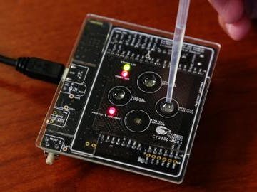
What is important to understand is that there is no firmware development for the MBR3 device family. The MBR3 devices are configured over I2C setting registers inside of the device to enable or disable certain features. On the MBR3 kit we support four CapSense buttons and one Proximity loop sensor. This kit can easily provide a CapSense front panel to your design.
We have provided in the download section of the post the EZ-Click project for the MBR3 kit and the Arduino sketch that supports both the Uno and the Mega formats.
The EZ-Click project provides all of the configuration values for the CapSense buttons and settings. The output file is used in the Arduino sketch to configure the MBR3 device.
The Arduino code configures the MBR3 over I2C (two wire interface) using the 128 byte configuration data generated using the EZ-Click tool. The code uses the Arduino built in library called “wire” for the I2C communication. Here the Arduino board behaves as master and the MBR3 silicon will be a Slave on the I2C bus. The 128 bytes of configuration data is copied from the EZ-Click generated IIC file and loaded in the configdata[] array.
The wire I2C library has a limitation that only a maximum of 32 bytes can be sent by a single call of wire.write (&data,num_of_bytes). Hence in the Arduino code we sets of 31 bytes of configuration Data along with the one byte offset address until all the 128 bytes are sent.
After this is complete we send the SAVE_CHECK_CRC and SW_RESET commands for the MBR3 device to save the configuration data and apply the new loaded configuration. The Arduino code uses the pin 2 interrupt feature on Arduino board and Host interrupt feature on CY3280-MBR3 board to determine when to read the button status and display the same on serial monitor. The MBR3 kit provides a low pulse (HIGH->LOW->HIGH) on the Host_INT pin whenever a sensor touch or proximity status changes.
Attached to this example is an example guide that can help you navigate through the example.
Hardware Connections:
For this example the user will need to connect the CY3280-MBR3 evaluation kit to the Arduino Uno or Mega boards.
Note: When using CY3280-MBR3 with Uno please short R71 and R72 zero pads. This is because the Uno board has the I2C lines on J2 instead of J3.
The CY3280-MBR3 has a number of configurable options via jumpers. Please make sure that the jumpers are in the following configurations:
- Shunt the jumper J11-1 to J11-2
- Shunt the jumper J12-1 to J12-2
- Shunt the I2C selection jumper J13 between J13-2 and J13-3
- Shunt the I2C selection jumper J14 between J14-2 and J14-3.
- Jumper 15: Keep the jumper J15 in configuration A as indicated on the board silkscreen using the 3 shunts i.e.
- Shunt J15-1 to J15-2
- Shunt J15-3 to J15-4
- Shunt J15-5 to J15-6
Test Your Project:
Program the Arduino Uno or Mega development kit with the Sketch and power up the kit. The Arduino base board will communicate to the CY3280-MBR3 kit, configuring the device over I2C and then monitor the device for any button touches on the kit. These button touches will correspond to LED flashes on the CY3280-MBR3 Kit. The button status from the MBR3 kit can be monitored on the serial monitor of the Arduino IDE.
I hope this example project helps you. We will have more information on the MBR3 kit in the coming days. We will include examples on how to use the MBR3 kit with your Pioneer Board. Stay tuned!
- MBR3 - Arduino_HOST_INT.zip 3.2 K
- Arduino Sketch - MBR3_Read_Status.zip 3.1 K
- Example Steps Guide.doc 529.5 K


Comments