


Hardware components | ||||||
 |
| × | 1 | |||
| × | 1 | ||||
 |
| × | 1 | |||
| × | 1 | ||||
| × | 1 | ||||
| × | 1 | ||||
Hand tools and fabrication machines | ||||||
 |
| |||||
 |
| |||||
| ||||||
| ||||||
| ||||||
Earlier this year I attended a Hackster.io Hardware Meetup - SF workshop where we built the circuit for a LED strip bike light. That night I completed it, shoved it into an Altoids tin, and zipped tied it to the rear of my bike before riding to the ferry. After a few weeks of putting it through its paces, connections started separating, the zip ties weren't holding the tin in place anymore, the strip started to bend, etc. So I decided to make a robust and nicer looking tail light.
Some of instructions here are the exact same instructions I followed at the meetup, primarily those about building the circuit. This project brings that information together with the structural aspect of the light to result in a tail light that is quite solid.
Build the CircuitTo build the circuit, follow these instructions that were provided at the meetup. Eventually it will be taken apart, cut, and soldered together. So make sure that it works with the battery. If it isn't tested before assembly, it will be very difficult to troubleshoot. Label the wires with small pieces of tape or something so that it's easy to know what goes where.
3D Print the HousingAttached is the STL for the bicycle rear tail light. It has plenty of room for a single ATTiny85, wires, resistor, and an LED strip. I used transparent filament which ends up looking like white. It helps increase the illumination spread just a bit.
I have an Ultimaker 2 so I use Cura to slice. This means the following instructions are specific to Cura.
- Lay the light down flat along its backside and rotate to fit nicely in the bed
- Shell thickness: 1.2
- Disable retraction (this is because my filament gets chewed up by the knurled feed wheel)
- Support type: Everywhere
- Platform adhesion: None (make sure to use kapton tape or glue stick)
- Fill Density: 75 (this makes the piece very solid)
Print time: Cura says 4.5 hours, in reality 8 hours.
After the print job, there will be some stringing and supports that need to be removed. The best way I've found is to use a variety of picks to pull off or dig out the supports and then use rasps or emery boards to knock down the stuff sticking out. A Dremel helps when needing to knock something down in a tight space. Keep in mind, however, that the bit rotation speed in contact with the housing may cause too much heat and possibly melt the area.
Carefully disassemble the circuit. Start soldering everything together triple checking if the wire is connecting to the right part. Make sure to feed the USB power cable through the side hole BEFORE soldering its wires in place.
Once everything is soldered, test it with the battery. If it doesn't work, troubleshoot.
AssembleCut away the unused pins in the ATTiny85. Using electrical tape, wrap everything securely but don't overwrap where it's too bulky. Shove the circuit in the cavity. Hot glue the LED strip in place along the channel, the sides, and the ends. The glue should act as a water barrier so nothing gets inside the cavity.
Now test it with the battery. Cross your fingers. It's hard to troubleshoot if it doesn't light at this point.
MountThe final step. Mount the tail light. I have a rear rack which has mounting holes. And it just so happens that the holes in the tail light match up with the mounting holes. Go figure.
Simply bolt the tail light onto the rack. Then use the rubber band to secure the power bank onto the tail light. Using a rubber band to secure the power bank makes it simple to remove the bank when the bank needs to be recharged.
This is what it looked like the night of the meetup.
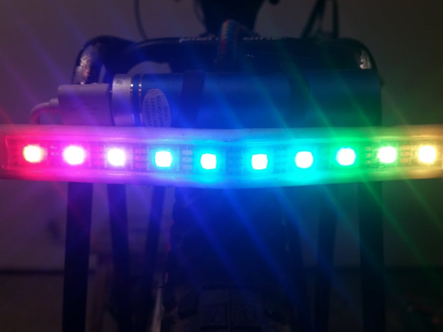
This is what it looks like now.


Comments
Please log in or sign up to comment.