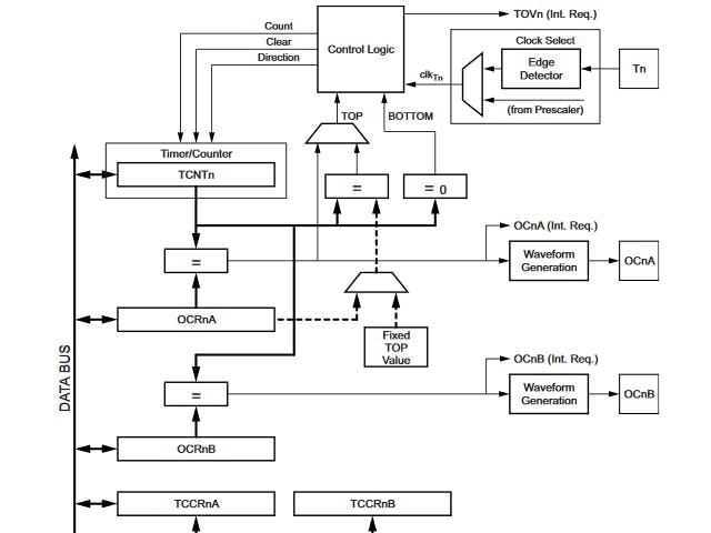
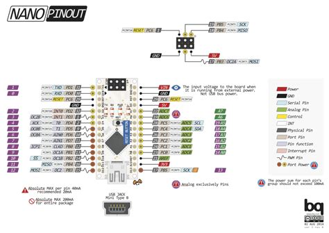
Nearly all projects that utilize a microcontroller have some kind of time-dependent component, such as a delay or repeating task. Internal timer circuits enable this functionality by counting up on every pulse it gets, either from a prescaler or a clock directly.
By getting the value of this counter, you can determine how much time has elapsed. For example, if an MCU's clock is set to 125KHz, one of its timer is set to use that clock, and its prescaler is set to 1/1024, then each increment of its counter register is equal to about 1/122 seconds, which is derived from:
t = 1 / (CLK / prescaler)
so (1/122) = 1 / (125000 / 1024)
In case you are curious, the job of the prescaler is to divide incoming clock pulses by a certain value, which slows down the counter by that factor. So a timer that has a prescale value of 4 will see a system clock of 8Mhz as 2MHz instead. Arduino's millis(), delay(), and micros() all rely on these timers to operate. But there is an issue: delay() is blocking, and to make it non-blocking, you have to check the millis()'s value in each loop.
Using Interrupts InsteadTo avoid this issue, the ATmega328P's timers can be set to trigger interrupts on several different triggers. One of these is the overflow flag, which is set whenever the counter register rolls over to 0 from its max value, such as an 8-bit register going from 255 to 0. Another way to trigger an interrupt is by using compare registers, which store a value that is continually checked against against the counter, and raises an interrupt whenever that value is reached by the counter. Microcontrollers such as the ATmega328P use this kind of function to control PWM on pins, and other, more advanced MCUs, are able to directly toggle pins from the timer without needing the CPU at all.
Setting Up the HardwareFor this example, I created a simple program that sets a compare value for the ATmega328P's Timer/Counter2, fires an interrupt on compare match A, and toggles the value of a pin. All of the details for this can be found in the microcontroller's datasheet. The code starts by calling the hardware_setup() function, in which several registers are set to configure the system, timer, and pin. Digital pin 2 is set as an output by placing the value of (1 << DDD2) into the DDRD register. Next, timer 2's prescaler is set by putting ones into the clock select bit fields for the TCCR2B register, setting the prescaler to 1/1024.
Next, a value of 255 is placed into the compare register A (OCR2A), which means that an event will occur when the counter gets to 255. The TIMSK2 register gets a value of (1 << OCIE2A) placed into it, which lets timer 2 output an interrupt when compare match A is triggered. Finally, TCCR2A gets a value of (1 << COM2A0) that toggles D12 on each compare match as well.
Although we set the TIMSK2 register to trigger an interrupt, it still needs to be handled. This is accomplished by creating an ISR (Interrupt Service Routine) that will trigger when the interrupt is raised. In the attached code, the ISR increments a counter and clears the flag. In the while loop in main(), the counter variable is checked to see when it reaches 100, and if it does, then the value for D2 is toggled by performing an XOR operation like so: PORTD ^= (1 << PORTD2);
It is important to make the count variable volatile because it tells the compiler that its value can be changed at any time outside of the program's normal path of execution. The program should be flashed via a programmer to the Nano. Don't use Arduino functions with custom timers, as this can mess up both your timer and the builtin functions.
With this code, an LED attached to pin 2 should blink every 2.5 seconds. Try changing different values or setting up other timers in various modes.


Comments
Please log in or sign up to comment.