Ever needed to control many outputs but didn’t have enough GPIO pins? What about using 16 LEDs with only 5 pins? This is where a multiplexer is useful.
Multiplexers (MUX for short) take in a common input or output and send that signal to one of its output pins. The pin is selected by setting the control pins to either high or low. If it’s an 8-channel MUX, then it will have 3 control pins, because 23 = 8. Setting S0 to 1, S1 to 0, and S2 to 1 would cause pin 5 to become active, because in binary, 101 = 5.
Why They Are UsefulMultiplexer allow for microcontrollers that have limited IO to control much larger systems without the need for external processors. Imagine being able to control a 4x4 LED matrix with just 5 pins instead of 8 or 16.
I chose the 16-channel CD74HC4067 MUX for this project due to its ease-of-use and generous amount of IO. For the microcontroller, I went with the ATtiny85. In order to display which outputs were high, I also included 16 LEDs and 220ohm resistors.
Sparkfun has an Eagle library that contains the CD74HC4067 IC, but it is not the correct package. The MUX I used was in the SO24-wide package, whereas Sparkfun’s was SSOP24. Because of this incompatibility, I had to create my own part using Eagle’s library creator tool. I began by creating a new part and selecting a package. The “ref-packages” library in Eagle has package footprints for nearly any IC, so I was able to easily find the SO24W footprint and import it.
Next, I added its symbol by importing Sparkfun’s own CD74HC4067 part.
Lastly, I connected the pins from the symbol to the pads on the package by using Eagle’s Connect dialog.
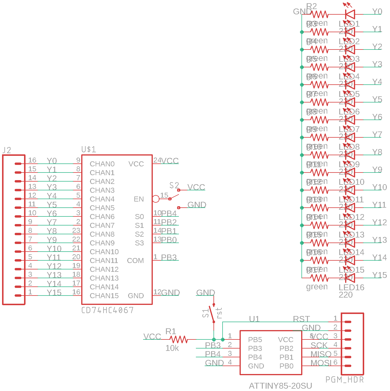
The circuit for this project is quite simple. The ATtiny85 is connected to a programming header so that programs can be flashed, and it is also linked to the MUX.
The multiplexer can be enabled or disabled by toggling a switch, and each output pin connects to both a pin header and LED for easy viewing.
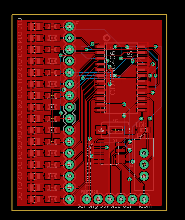
Designing a BoardDesigning the PCB in Eagle was easy. I began arranging the MUX and ATtiny85 next to each other, then I placed the two pin headers and switch.
Because each LED corresponds to an output pin, I laid them out directly next to each pin on the header. Lastly, I placed the reset button and its 10k pullup resistor just above the ATtiny.
After receiving the board from OSH Park, it was time to assemble.
When soldering SMD components, it is best to start with the smallest components and work your way up to the larger ones. This prevents having to reach around larger components and having your line-of-sight blocked.
To program the board, I started by wiring up an Arduino Nano to act as a programmer. Next, I uploaded the ArduinoISP sketch to the Nano, which allows it to send new firmware to the ATtiny via its SPI interface. Make sure to place a 10uF capacitor between the Reset and GND pins of the Arduino Nano to program the ATtiny.
Here’s a table of pins and connections used:
ATTiny85    |   Nano
VCC         |   5V
GND         |   GND
MOSI        |   11
MISO        |   12
SCK         |   13
RST         |   10
Then I added the ATtiny boards to the Arduino IDE by placing this URL (https://raw.githubusercontent.com/damellis/attiny/ide-1.6.x-boards-manager/package_damellis_attiny_index.json) into the Additional Boards textbox in Preferences and installing it in the Boards Manager. Simply select the ATtiny85 chip, 8MHz internal clock, and Arduino as ISP for the programmer.
The program I created simply increments a variable from 0 to 15 and then loops back to 0. At each number, it goes through each pin and checks if that pin should be active through some bitwise operations.
I plan on using this board to connect multiple buttons to an ATtiny85 to perform various functions.


Comments
Please log in or sign up to comment.