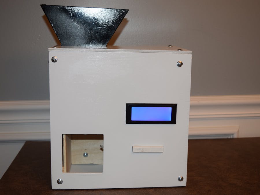
The aim of this project was to improve on my previous candy dispenser by making a new one that is more interactive and aesthetically pleasing.
Video:
A Little BackgroundIn early May I published a project documenting my building and usage of a candy dispenser that I had built as part of being a beta tester for the Google AIY Projects Kit. It was well received, garnering about 3 thousand views in just 2 weeks, and 4 articles being written on it.
Overall, it was a worthwhile and successful project, but I wasn’t satisfied. The Maker Community can be summed up with this saying: “Have an idea, create the product, and innovate on it.” I decided that a basic box with limited functionality was nowhere near as exciting as it needed to be. So I set out to build a better, smarter, and more connected machine. This time it would be a lot easier, as I had just finished building a new CNC router (the MillRight CNC M3 kit), which would enable me to create much more precise parts with a higher degree of aesthetics and accuracy, rather than using a jigsaw.
Up to this point, I have had quite a bit of experience with my favorite CAD program- Fusion 360. It has everything a maker needs in its workflow to go from an idea to a finished part in CAM. I knew I would have to build something sleeker and more modern, along with using fewer parts. I started out with making a simple box, and finding out how I should arrange a button and LCD to allow for user interaction.
Next was finding the right board to use for running it. I decided upon using a Raspberry Pi Zero W due to its small size and wireless capabilities.
I also chose to use a stepper motor to drive a paddle which would dispense wrapped candy from a funnel. Next, I thought to myself: “How do I add an interesting way to interact with this device?” I had already used Google Assistant, so why not use Twitter? The latest tweet shows up on the LCD, along with whom it’s from. Now that I have a design, it’s time to start building it!
Manufacturing the PartsThe first step in creating a part is making sure it will fit. My design fits in a 10.5 inch cube (26.67 cm),which is the maximum size my router can handle. To generate the gcode I used the CAM environment that is built into Fusion 360. I created a setup for each part, setting my stock to be 266.7mm by 266.7mm and 20mm thick. I did this because my material is ¼ inch thick (6.35mm), therefore ensuring that the bit will cut all the way through. After generating a setup, I then configured the path for cutting out the part. I chose a 2d contour and set the speed to 18000 rpm because I was using the DeWalt DWP611 Router. There are more settings as well but I won’t go into that. For more information go to the resources page here: https://www.millrightcnc.com/resources
To get the parts go to: https://gallery.autodesk.com/projects/99462/candy-dispenser-2 to view and download the parts for CNC routing.
I cut out the pieces and sanded them down thoroughly, ensuring I wouldn’t get any splinters and the paint would stick. Next, I coated the outer pieces with 2 coats of sprayable shellac, and then sanded once more to even out the surfaces. Finally, I gave each piece three coats of laquer spray paint. I painted the box part white, and the funnel black.
I also 3D printed a paddle for the stepper motor and a button that slots into the front plate.
You can find those designs here: https://www.thingiverse.com/thing:2426514
Software and HardwareBecause I had chosen to use the Raspberry Pi Zero W in my project, I had to set it up first. To accomplish that, I wrote the latest Raspbian Jessie with PIXEL (https://www.raspberrypi.org/downloads/) onto a 16GB SD card. Then I booted up the Raspberry Pi and waited for the green light to go solid (all files had been written). I shut down the board and removed the SD card, inserting it into a computer running Linux (so I could see all of the files on the ext4 filesystem). To enable SSH I made a blank file (NO extensions) and named it “ssh”, and I also created a new text file called “wpa_supplican.conf”. In it I put:
network={ssid="SSID" psk="PASSWORD" key_mgmt=WPA-PSK }
Now, reboot the Raspberry Pi Zero W and SSH into it. Enter:
sudo raspi-config
and enable VNC and UART. Exit and reboot it again. Now, SSH and enter vncserver
then sudo startx
. Exit out of that session and open VNC Viewer on your PC. You are now completely set up and ready to run some code!
Start by downloading the files I included, which includes the “main.py” file. Run
sudo apt-get update
and then
sudo apt-get install build-essential python-dev python-smbus python-pip git
Make sure RPi.GPIO is installed with
sudo python2 -m pip install
Next install the LCD library by running:
cd ~
git clone https://github.com/adafruit/Adafruit_Python_CharLCD.git
cd Adafruit_Python_CharLCD
sudo python2 setup.py install
Then, go to https://apps.twitter.com and create a new app. Put in the name, description, and a phony website. Next, go to the “Keys and Access Tokens” section, and generate the oauth access tokens. Paste those into in the order of: Consumer Key, Consumer Secret, Access Token, and finally Access Token Secret.
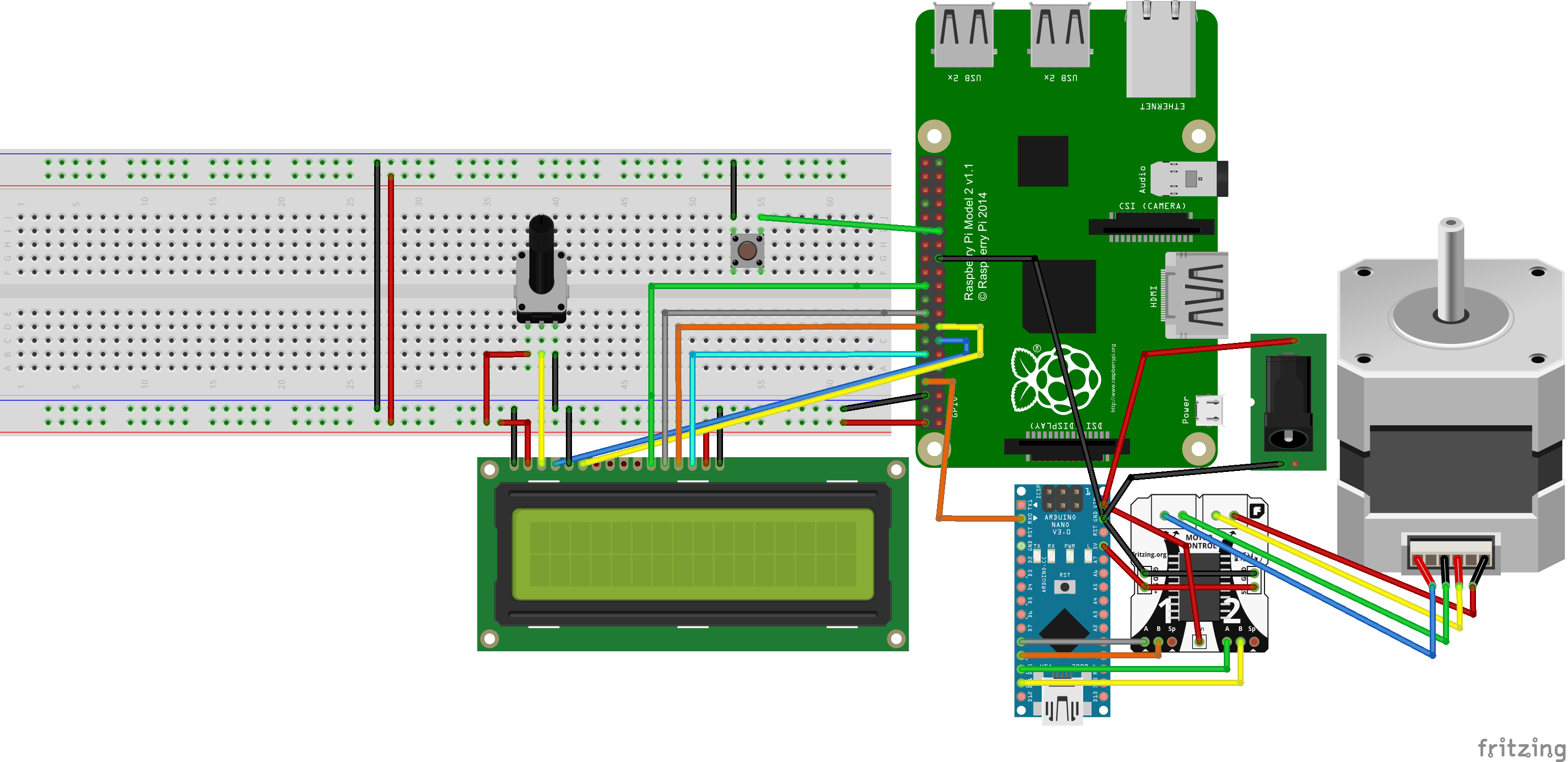
Now that the software side is done, it is time to wire everything together. Start by connecting the LCD to the Pi.
Pi (BCM Pin Mapping)  |   LCD
27  |  RS
22  |  EN
25  |  D4
24  |  D5
23  |  D6
18  |  D7
4   |  Backlight (not used)
Potentiometer Wiper (middle pin)  |  V0 (contrast)
+5v  |  VDD, Backlight +, Potentiometer +
GND  |  VSS, R/W, Backlight -, Potentiometer -
Connect a pushbutton (tact switch) to Pi pin 5 and GND, along with a common cathode RGB LED. Red: 16, Green: 20, Blue: 21. Also attach an Arduino Nano’s GND to the Pi’s GND, along with a jumper going from Pi UART Tx (pin 14) to the Nano’s Rx.
For the stepper motor, connect coil pair A to l293d outputs 1 and 2. Connect pair B to outputs 3 and 4. Attach inputs 1,2,3,4 to the Nano’s pins 8,9,10,11, along with connecting their GNDs. Get a 12v power supply (I used a 12v adapter with a DC barrel jack) and connect it to both the l293d and VIn, along with its GND going to the Nano and the driver. That’s it! Now the wiring is now complete.
Putting It All TogetherGo ahead and assemble the parts together. I used screws and wooden blocks to secure the parts together, and it enables for the machine to be taken apart easily.
Now, you can tweet at it: “@(your Twitter app handle) (a phrase with ‘color’ and ‘red’, ‘green’ or ‘blue’)” to change the color of the LED, or just tweet anything!
Push the button to rotate the inside paddle to dispense candy. Have fun with your new Raspberry Pi Powered Candy Dispenser.


_t9PF3orMPd.png?auto=compress%2Cformat&w=40&h=40&fit=fillmax&bg=fff&dpr=2)


_3u05Tpwasz.png?auto=compress%2Cformat&w=40&h=40&fit=fillmax&bg=fff&dpr=2)

Comments
Please log in or sign up to comment.