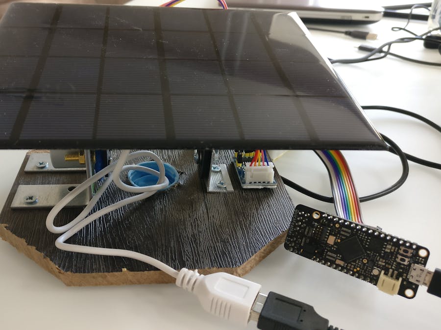
For save our planet need use more revenue energy, like solar power. I make prototype solar tracker, it give us more efficient generate energy.
The generated electricity from fixed tilt angle solar array is less efficient throughout the day as the solar array is not facing the Sun directly (optimum angle) all the time. Sun moves 15 degrees every hour from East to West across the equator. The larger the angle difference between sunlight incidence and solar panels facing, the larger the losses based on cosine formula.
Secondly, due to the tilting of earth's axis of rotation, the Sun also moves with variation ± 23.5 ° in North-South direction across equator throughout the whole year. It will have slight losses even fixed array facing the optimum angle.
Making the chassisStart our work with will make Base.
Making a connection for the motor
We make the connection between the motor and the bracket
Installing the bracket
Result:
I use 28BYJ 48 5V with power driver on ULN2003.
What understand algorithm control, we will see inside motor sheme:
For control I choose on QuckFeather board that pins:
IO_31 mapped to GPIO 4
IO_23 mapped to GPIO 7
IO_30 mapped to GPIO 3
IO_28 mapped to GPIO 2
For control stepper motor we have three algorithm: wave, half-step and full-step. Diagram below:
I shoose last. I use exemple from gitHub qorc-sdk\qf_apps\qf_helloworldsw and modification it. Part code - generate last diagram:
int dl = 5;

                        HAL_GPIO_Write(2, true);
			HAL_GPIO_Write(3, false);
			HAL_GPIO_Write(4, false);
			HAL_GPIO_Write(7, true);
			vTaskDelay(dl);

			HAL_GPIO_Write(2, true);
			HAL_GPIO_Write(3, true);
			HAL_GPIO_Write(4, false);
			HAL_GPIO_Write(7, false);
			vTaskDelay(dl);

			HAL_GPIO_Write(2, false);
			HAL_GPIO_Write(3, true);
			HAL_GPIO_Write(4, true);
			HAL_GPIO_Write(7, false);
			vTaskDelay(dl);

			HAL_GPIO_Write(2, false);
			HAL_GPIO_Write(3, false);
			HAL_GPIO_Write(4, true);
			HAL_GPIO_Write(7, true);
			vTaskDelay(dl);
Variable dl - deley, change speed rotate stepper motor.
for use pin IO_31, IO_23, IO_30, IO_28 I add to pin_cfg_table.c add block each pin.
// Stepper motor pins
  { // setup pin steper motor
    .ucPin = PAD_31,
    .ucFunc = PAD31_FUNC_SEL_GPIO_4,
    .ucCtrl = PAD_CTRL_SRC_A0,
    .ucMode = PAD_MODE_OUTPUT_EN,
    .ucPull = PAD_NOPULL,
    .ucDrv = PAD_DRV_STRENGTH_4MA,
    .ucSpeed = PAD_SLEW_RATE_SLOW,
    .ucSmtTrg = PAD_SMT_TRIG_DIS,
  },
  { // setup pin steper motor
    .ucPin = PAD_23,
    .ucFunc = PAD23_FUNC_SEL_GPIO_7,
    .ucCtrl = PAD_CTRL_SRC_A0,
    .ucMode = PAD_MODE_OUTPUT_EN,
    .ucPull = PAD_NOPULL,
    .ucDrv = PAD_DRV_STRENGTH_4MA,
    .ucSpeed = PAD_SLEW_RATE_SLOW,
    .ucSmtTrg = PAD_SMT_TRIG_DIS,
  },
  { // setup pin steper motor
    .ucPin = PAD_30,
    .ucFunc = PAD30_FUNC_SEL_GPIO_3,
    .ucCtrl = PAD_CTRL_SRC_A0,
    .ucMode = PAD_MODE_OUTPUT_EN,
    .ucPull = PAD_NOPULL,
    .ucDrv = PAD_DRV_STRENGTH_4MA,
    .ucSpeed = PAD_SLEW_RATE_SLOW,
    .ucSmtTrg = PAD_SMT_TRIG_DIS,
  },
    { // setup pin steper motor
    .ucPin = PAD_28,
    .ucFunc = PAD28_FUNC_SEL_GPIO_2,
    .ucCtrl = PAD_CTRL_SRC_A0,
    .ucMode = PAD_MODE_OUTPUT_EN,
    .ucPull = PAD_NOPULL,
    .ucDrv = PAD_DRV_STRENGTH_4MA,
    .ucSpeed = PAD_SLEW_RATE_SLOW,
    .ucSmtTrg = PAD_SMT_TRIG_DIS,
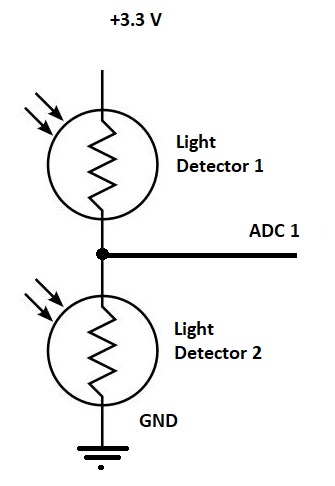
},To take data on the amount of light - I use photoresistor and ADC1 input on QuckFeather board.
Photoresistor below:
For test use ADC1 convertor I use that code:
static void checkAnalogInput(const struct cli_cmd_entry *pEntry)
{
    uint16_t iCurrentBatteryLevel = 0;    ///< 12-bit integer from ADC conversion unit
    char snum[5];

    (void)pEntry;
    HAL_ADC_Init(ADC_CHANNEL_1, 1); // Enable photo measurement
    HAL_ADC_StartConversion(); // start ADC conversion
    vTaskDelay(25);            // Conversion takes about 25ms
    HAL_ADC_GetData(&iCurrentBatteryLevel);  // get the ADC reading
    // convert 123 to string [buf]
    itoa(iCurrentBatteryLevel, snum, 10);

    CLI_puts(snum);
    return;
}
I add this method in main_dbg_cli qf_menu.c form project helloworldsw.
Connection to controller:
In middle point Light detectors is 1.5V this value was big for ADC and it to measure 4095. I add diode between 3.3 supply and top photoresistor. This shifted the working point.
I call function run ADC - checkadc.
CLI_CMD_SIMPLE( "checkadc", checkAnalogInput, "start solar track" )Exemple below:
For starting tracking for solar, I add commad - starttrack.
CLI_CMD_SIMPLE( "starttrack", starttrack, "start solar track" )Code you can see in gitHub.
Test work:
Glass break sensor.The solar panel can be damaged due to various reasons. We make sensor breakglass.
We can use SensiML Data Capture Lab and Using SensiML Analytic Studio. And learn our QuickFeather.
Open SensiML Data Capture Lab. Switch to Capture.
Add Device for capture. Choose QuickFeather Simple Stream, capture source - audio, choose checkbox Microphone. I take name Microphone. Next need click button Find Devices and after search choose number COM port. We will look what - QuickFeather Simple stream on COM7.
After need create Label use button Add label. I add two - ambient and breakglass. Choose current label and capture signal use button Begin Recording.
Next switch to Label Explorer, you give name session. I call - manual and take mode manual. After I separate to segment. You use mouse and right button for this.
Add each segment label in Segment table. Save project.
After we run SensiML Analytic Studio. And open our project.
All steps describe in documentation , my steps in screenshot below.
Check our result.
ConclusionThis tracker can use in autonomous power, for a example supply base station Helium network for advanced coverage network on Agricultural fields and street lighting in remote locations.


Comments
Please log in or sign up to comment.