Central air conditioning is a modern convenience that most would admit that they cannot live without. However, these systems can have limitations. Central air conditioning generally regulates temperature with one temperature sensor per floor, which is only a local approximation of the average temperature of the floor. A floor with many closed-door rooms with ducts in them may have a large variation in temperature between each room. Manual air conditioning dampers exist to help solve this issue, but these dampers are merely vents that can be manually set to different amounts of restriction to restrict hot air from flowing to the colder room. Again, this system has limitations, because the static dampers are set to an average reading, which has no ability to actively regulate the temperature in a room. The ultimate solution is to have a temperature sensor in every room, and regulate the flow of air to each room actively to maintain a constant temperature in every room. This problem poses a few obstacles that can be addressed. A thermostat is hard wired into one spot in the wall in a floor, which would make installing many active dampers a large and destructive job requiring lots of sheetrock to be removed. The solution is to have all of the electronics and damper packaged in the ceiling vent, which is easy to replace. The dampers can communicate wirelessly over the internet instead of being hard wired into the thermostat for ease of installation as well. In fact, the system does not need to know the temperature the thermostat is set to, but instead the temperature sensors can compare their values with one another and work in relative numbers.
This concept is tested with two IOT argons. These two argon are copies of each other to show the scalable nature of this idea. The argons each collect data from a temperature and humidity sensor, and control servo motors to open and close the vents. As just mentioned, humidity in the room is taken into account when controlling the vents in this model as well. The logic works as such: in the winter time, a colder room needs more heat than a warmer one. A room that is more humid than another is viewed as negative no matter the season. Of the two vents, the vent that has the higher temperature will read a one and the one with the colder temperature will read a zero. Similarly, the vent that has the lower humidity will read a one and the vent with the higher humidity will read a zero. These values are added together and passed through an if-then statement to decide when to open or close the vent. The statement says that if a vent reads a total value less than 1, the vent will close; otherwise the vent will remain open. This means that unless a room is both more humid and colder, the vent will remain open. Once the vent is commanded to close, the servo motor is commanded to rotate to a certain angle that fully closes the vent. This process loops every 10 seconds, and works digitally to balance the temperatures between rooms in the house. A more detailed description of the project exists below.
Below is a demonstration of the vents in use:
Below the video is still shots of important parts of the video. The first of these is the Thingspeak graphs produced by the boards:
Chart Key
Field 1: Temperature of vent 1 in Fahrenheit.
Field 2: Humidity of vent 1 in percent humidity
Field 3: Vent open plotter for vent 1. Y values of 1 and 0 mean the vent is open, 2 means the vent is closed.
Field 4: Temperature of vent 2 in Fahrenheit.
Field 5: Humidity of vent 2 in percent humidity
Field 6: Vent open plotter for vent 2. Y values of 1 and 0 mean the vent is open, 2 means the vent is closed.
Wiring and Fabrication
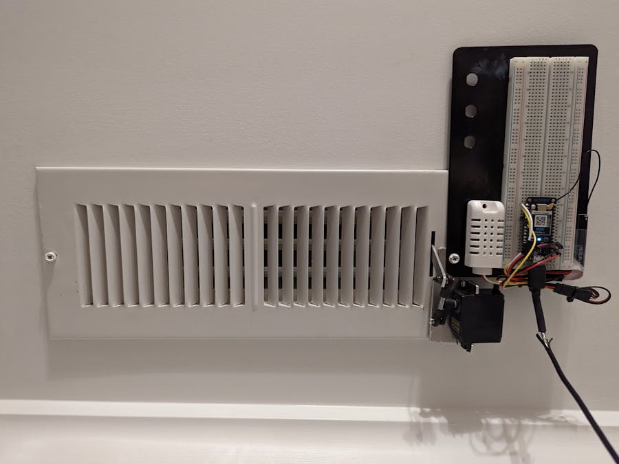
Below are images of the two vents. They are identical to each other.
Below is an image of the vent opening linkage:
This linkage is proprietary to this model vent. The mechanical advantage of the aluminum lever is critical to the functioning of the vent, as the servo motor has a limited amount of torque. With this linkage, I was even able to run the 7 volt servo off of the 3.3 volt source of the argon.
Programming Troubles
(Disclaimer: We are beginners at C and/or C++)
This project relies on the transfer of number values over the cloud, as opposed to boolean values that many Iot argon projects do. This operation turns out to be more of a challenge than one may think. The values the temperature and humidity sensors read is stored locally as an integer value. It is compared with a cloud-transferred integer to decide whether the vent will be open or not. However, the problem begins with the fact that integer values cannot be sent to the cloud, so instead they must be converted to a string to be sent to the cloud. This is done in the Particle.publish command: Particle.publish("roomtemperature2", String(fahrenheit2)); . The integer value that is read from the temperature sensor that was in the desired format is now converted to a string, which cannot be compared to an integer on the other board. The solution is to use the sscanf function to convert the cloud-transmitted string values back to integer values. This line of code does this: sscanf(data, "%d", &roomtemperature2); . This line reads as such: sscanf data from the Particle.subcribe data and print it to the roomtemperature2 variable in the integer format. The "%d" indicates the integer format.
Wiring Diagram
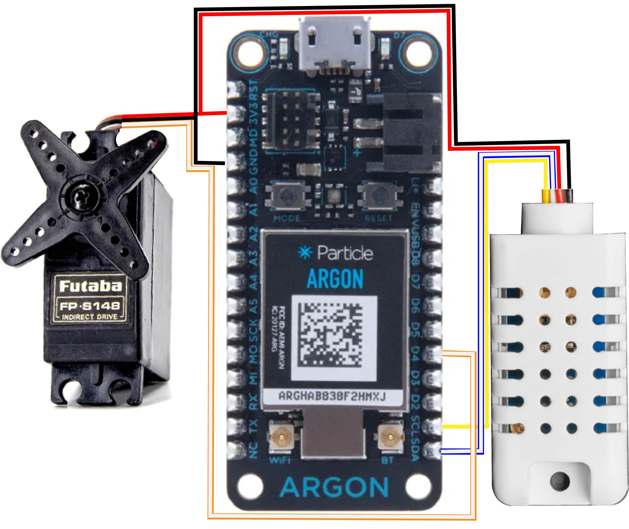
A wiring diagram is displayed below. The white plastic rectangle with the holes down the center of it is the SHT30 temperature sensor. It has four wires: black, red, white, and yellow. Black is wired to ground, red is wired to 3.3v power, white is wired to SDA, and yellow is wired to SCL. The Futaba servo is clearly labelled, and it has three wires: red, black, and white. Red is connected to 3.3v power, black is connected to ground, and white is the signal wire that is wired to pin D4.


_zhWsCcSEcl.jpg?auto=compress%2Cformat&w=48&h=48&fit=fill&bg=ffffff)


Comments