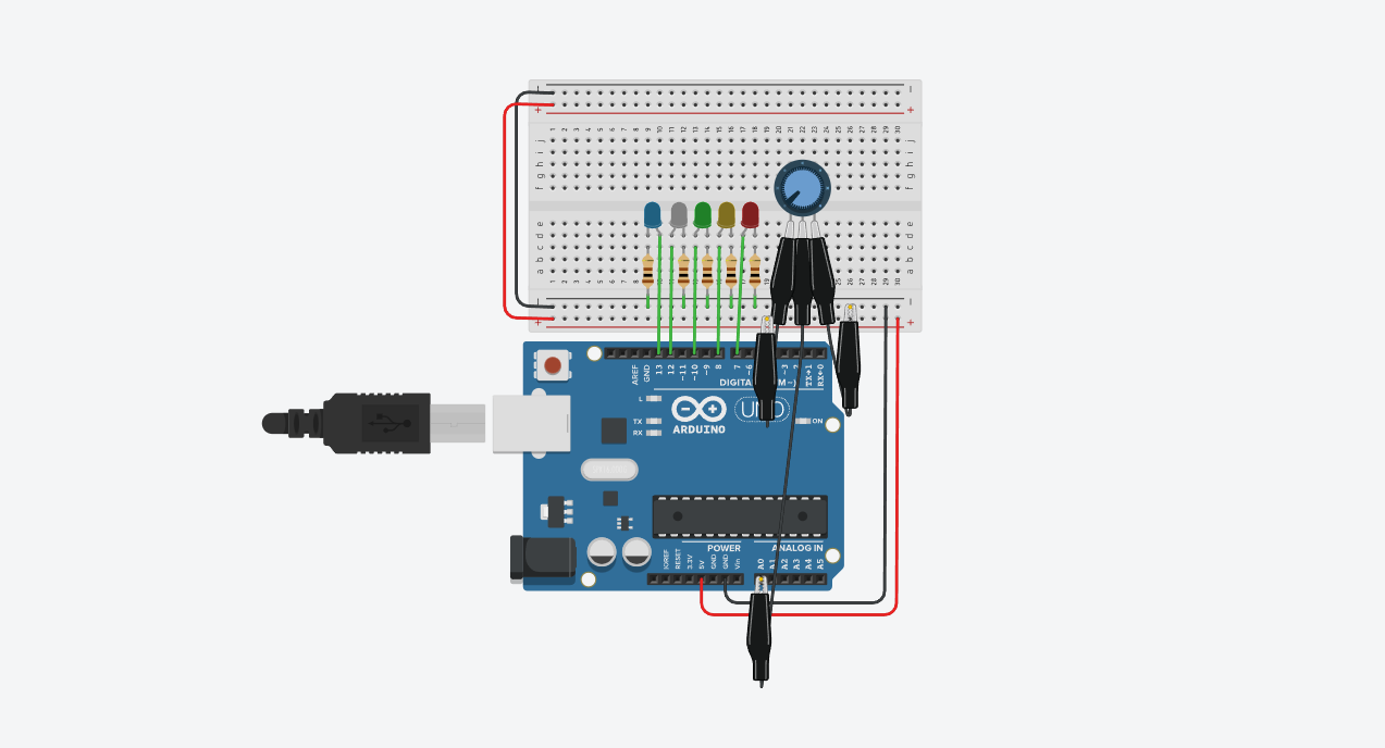
I set up an RSSI measurement circuit using an Arduino and a potentiometer. The potentiometer acted as the signal generator. The magnitude of the output voltage acted as the magnitude of the strength of the hypothetical signal received. The LEDs acted as a visual representation of the RSSI. The stronger the signal strength, the more LEDs light up.
How RSSI is measured ( in the real world)It is usually measured in decibels(dbm) relative to one milliWatt.
1. Signal reception - The receiver receives thesignal from the transmitter which could be a router or cell tower, et
2. Signal Power Calculation - The receiver measures the power of the received signal
3. Conversion to RSSI - The power measured is converted to RSSI. The RSSI scale is from -100dbm(weakest) to 0dbm(strongest). The formula is ;
RSSI=10×log10(P_reference/P_received)
P_reference is usally 1mW
1. It helps to determine the quality of a wireless connection. A higher RSSI values means a better connection.
2. Network Optimization - It can be used to dynamically adjust antenna positions, power levels, and even positioning of equipement so as to receive the best signal with the least inteference.
3. Bluetooth devices use RSSI to check the quality of connections and proximity. A common use case is in Bluetooth Low Evergy Beacons


_ztBMuBhMHo.jpg?auto=compress%2Cformat&w=48&h=48&fit=fill&bg=ffffff)


Comments
Please log in or sign up to comment.