


Hardware components | ||||||
 |
| × | 1 | |||
| × | 1 | ||||
| × | 1 | ||||
| × | 1 | ||||
| × | 1 | ||||
| × | 1 | ||||
| × | 2 | ||||
| × | 2 | ||||
| × | 1 | ||||
| × | 1 | ||||
| × | 1 | ||||
| × | 1 | ||||
| × | 2 | ||||
| × | 1 | ||||
My DS3231 drifts, I was doing the normal thing in updating it by compiling some code using system time, but this proved a bit inaccurate as the compiling and uploading kept getting interrupted by other processes happening on my computer.
After I found that GPS gave out accurate time (UTC) and date I decided to use that to set my DS3231.
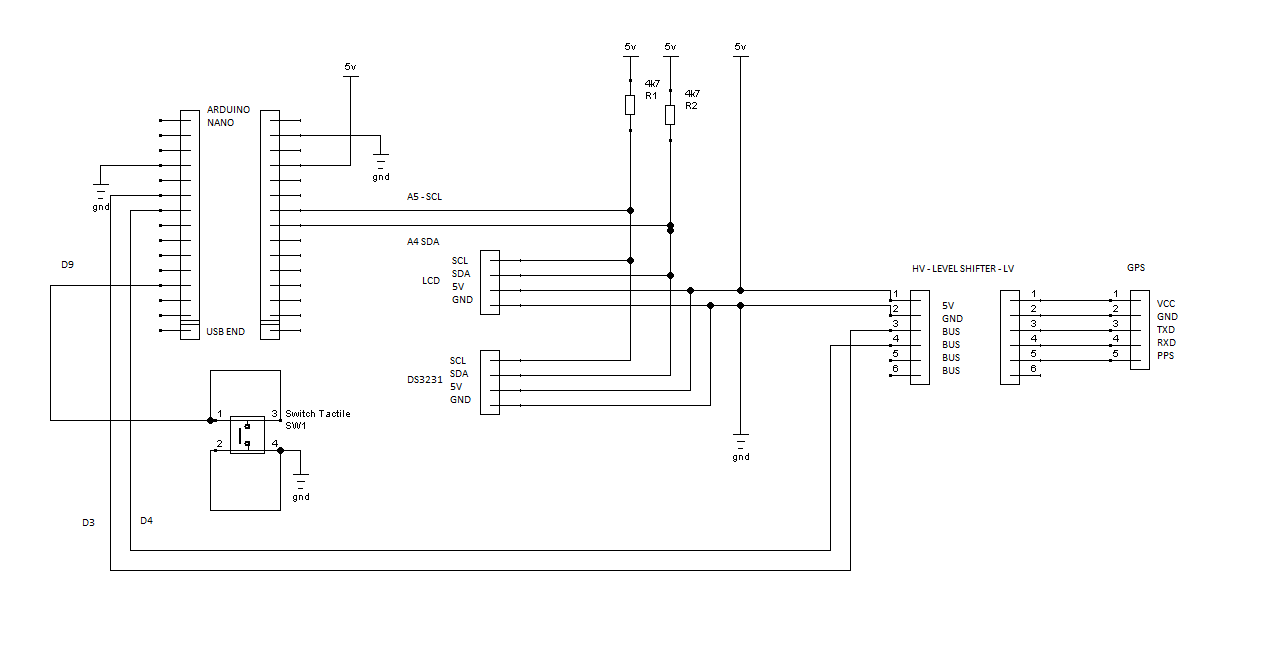
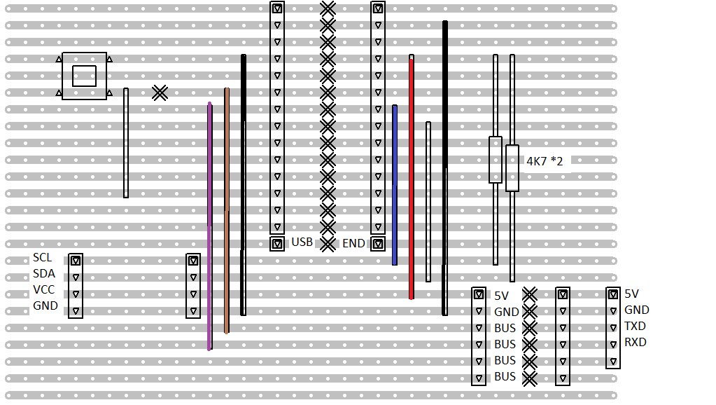
Circuit:LCD backpack to Arduino:
GND - GND
VCC - 5V
SDA - SDA (A4)
SCL - SCL (A5)
DS3231 clock module to Arduino:
GND - GND
VCC - 5V
SDA - SDA (A4)
SCL - SCL (A5)
LEVEL SHIFTER from Arduino:
5V - 5V
GND - GND
D3 - BUS
D4 - BUS
NEO 6M GPS from level shifter:
3V - VCC
GND - GND
BUS - TXD (ends up at D3)
BUS - RXD (ends up at D4)
SWITCH CONTACTS:
SWITCH - D9
SWITCH - GND
Power:I supply the power to my circuit through the USB cable.
Software:The 99% of the software is the parsing.ino example in the Adafruit GPS library. I added in a small amount of code to pass the extracted GPS date and time to the DS3231 and some additional code to display the time form the DS3231 on an LCD display.
Library’s used:Adafruit GPSLibrary by Adafruit version 1.0.3
RTCLib by Adafruit version 1.2.0
NewLiquidCrystalfor the I2C display backpack.
Operation:Turn the unit on.
The LCD will display the date and time values currently in the DS3231 registers.
Wait a while for the GPS to lock.
Press the button to set the time via the GPS signal.
The LCD will display the new time.
Operation limitations:The GPS unit does take time to lock and there is no indicator that lock has been achieved.Pressing the set button without lock resulted in my DS3231 date being set to2000:0:0 and the time to 0:0:0.
After the red LED on the GPS unit starts to blink seems to be the best time to press the set button – this can be into 10’s of minutes (indoors).
Initially the DS3231 unit I used had a flat battery, on pressing set the date was set to2000:0:0 and the time to 0:164:164. It took quite a while for the battery to get enough charge to accept the GPS data and continue ticking away correctly on its own.
GPS quirks:The board I purchased said simply NEO 6M GPS and has the connecting pins marked with their functions. I took a look at the datasheet for the device [1] and that stated the device functioned on around 3V, hence my use of a level shifter. However on closer inspection I found a 4A2D chip soldered to the board, an internet search shows it to be a voltage regulator but this does not guarantee that the communication lines are level shifted (my unit came with no circuit diagram).
I have also read on line that different GPS modules vary in their ability to receive a good signal indoors, hence my addition of an LCD display so I could take it outside.
LCD quirk:I am using one of the oddball ones that have an I2C address of 0x3F, most use the address 0x27, so if you see nothing try altering that first.
Library quirk:The libraryRTCLib (Adafruit version 1.2.0) sets the time and date registers but not the day register of the DS3231. The library has a function to return the day of the week which is calculated on the fly using the values in the date register.
I found this odd but realized eventually that it makes sense, setting the day register would require that your code be set up to alter it on leap years while generating the day by a formula avoids this.
UTC & Local time:I did a search on UTC and found that no change was required for my local time, so if you need it you will have to add in that bit of code yourself.
References:[1] https://www.u-blox.com/sites/default/files/products/documents/NEO-6_DataSheet_(GPS.G6-HW-09005).pdf(retrieved /Dec/2018)


Comments
Please log in or sign up to comment.