


Hardware components | ||||||
_ztBMuBhMHo.jpg?auto=compress%2Cformat&w=48&h=48&fit=fill&bg=ffffff) |
| × | 1 | |||
| × | 1 | ||||
| × | 1 | ||||
| × | 1 | ||||
| × | 1 | ||||
| × | 2 | ||||
Software apps and online services | ||||||
 |
| |||||
Some years ago I built a small movement alarm using a shock switch, a couple of LED’s, a piezo sounder element and a PIC microcontroller, I decided to revisit this project using the Arduino with a few alterations on the way.
When I did my initial design I focused on the behaviours I wanted my alarm to exhibit.
- The alarm should have a delay to allow it to be set in place.
- If the sensors are tripped during placement the delay is reset and restarted.
Once set:
- When tripped there is a delay before the alarm is sounded, to allow a legitimate user to disable the alarm.
- The alarm will sound for a set time.
- Each further time it is disturbed a LED will light for 5 seconds to allow the legitimate user to see it has been tripped but the alarm will not sound.
My original design used a shock switch which worked fine but the switch itself contains the toxic heavy metal mercury, so this time around I decided to replace that switch with 2 non mercury tilt switches.
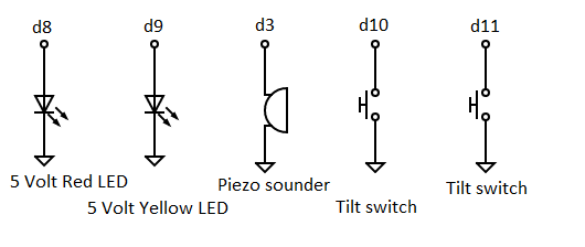
Circuit description:My circuit comprises 2 * 5 Volt LED’s (one yellow one red), a piezo sounder element and 2 non mercury tilt switches in addition to an Arduino UNO.
My goal was to use the minimum of components hence the 5 Volt LED’s with their built in resistors.
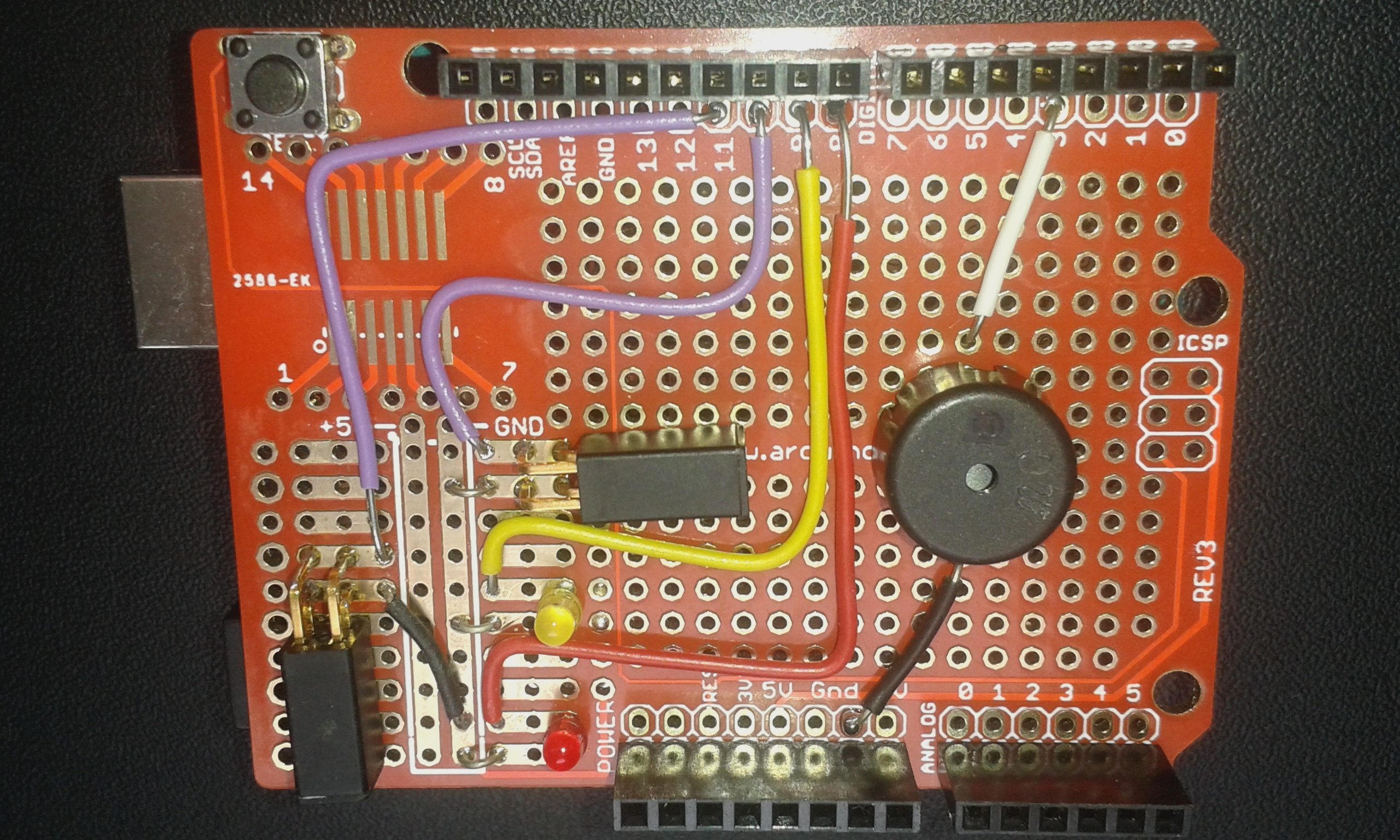
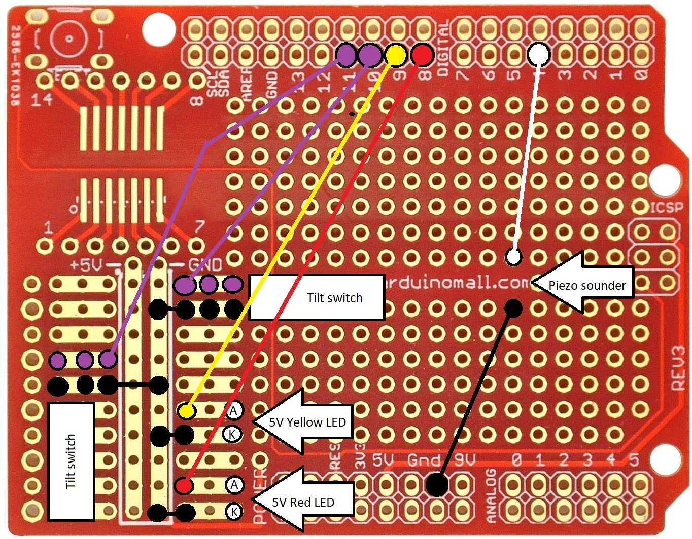
Board:I built the circuit onto an Arduino development shield board, I specifically chose the board as it had a block of Dual In Line solder pads which I felt would make the wiring up easier. The DIL solder pads were used for the 5 volt LED's and tilt switches, the sounder was placed elsewhere on the board and is the only component wired up directly to the component leads.
Software:The code consists of a main line handling the LED's and sounder and an interrupt service routing handling the tilt switches and time delay.
The timer code was created using an on line calculator [1].
Sensitivity:The tilt switches are at their maximum sensitivity when the circuit is placed on a flat surface; if placed flat on a table top, say, a gentle tap of the table will be enough to set off the alarm.
I tried a couple of software fixes to this sensitivity problem but had no success:
- lowering the frequency at which the timer polls the switches
- increasing the size of the debounce matrix so that any switch closure needs to occur for longer before registering; I note this is a bad idea as it conflicts with the principle that interrupt service routines be as short as possible
I did wonder if the problem was asymmetry in that when a switch closes it takes 10 clock ticks before it is registered but the opening of a switch takes a single clock tick to register but did not pursued this.
On tilt switches with flexible leads you can bend the body so that the ball has to run up, or down, a ramp to reduce sensitivity but the rigid leads of the switches chosen here precludes this.
[1] https://www.arduinoslovakia.eu/application/timer-calculator
Tilt alarm board photo


Comments
Please log in or sign up to comment.