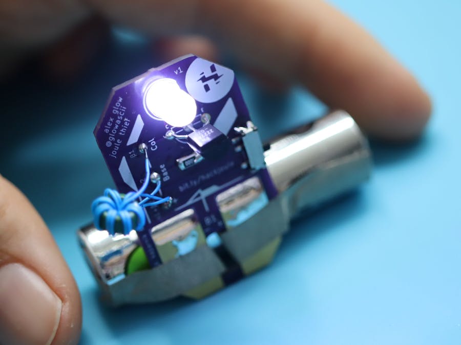
Get it on OSH Park here!
Build an LED tea light adapter using this board and a 3D-printed candle holder!
Or a pretty little light-up origami bouquet!
Here's a tutorial on how I do the aesthetic/graphical designs for my PCBs in Procreate on the iPad!
I feel a special connection to this circuit – whether you call it the "One-Volt LED" (named by Z. Kaparnik in 1999), or the "Vampire Micro Torch" or "Joule Thief" (designed in 2002 by Big Clive). The essence of this popular circuit comes from Kaparnik's article in Everyday Practical Electronics, which included schematics for a "Bright Light" that will power LEDs for ages, pulling the leftover energy out of a nearly-dead 1.2V or 1.5V battery. It's a truly magical little circuit, and versatile enough to work with a broad range of odd NPN transistors, salvaged ferrite cores, and "unusable" batteries. Sustainability heaven!
What's cool for me is that Kaparnik wrote in from Swindon, Wiltshire in the UK – which happens to be my birthplace, and where my bio-dad first introduced me to electronics. The county is home to a number of beautiful and mysterious phenomena, including Stonehenge and other Neolithic standing stone circles, crop circles, and huge figures of horses carved into the chalk hills. (Not to mention the ruined castles!) Altogether, it's the perfect place for this "vampire" circuit to originate – and also seems to fit in with the locals' reputation for getting away with things they shouldn't. :)
...I also have to mention the Magic Roundabout, which is definitely traffic sorcery and another good name for this circuit!
OK, OK... it's really not ALL that mysterious. But I do think this circuit tickles our minds because it has a certain mysterious beauty, with its cycles of feedback, collapse, and decay, the interplay of electricity and magnetism, and so on. Despite its relatively simple construction, its behavior is complex and powerful.
So... how does it work? I'll give my (heavily simplified) take, but you might also like to check out this video by RimstarOrg, which really helped me understand:
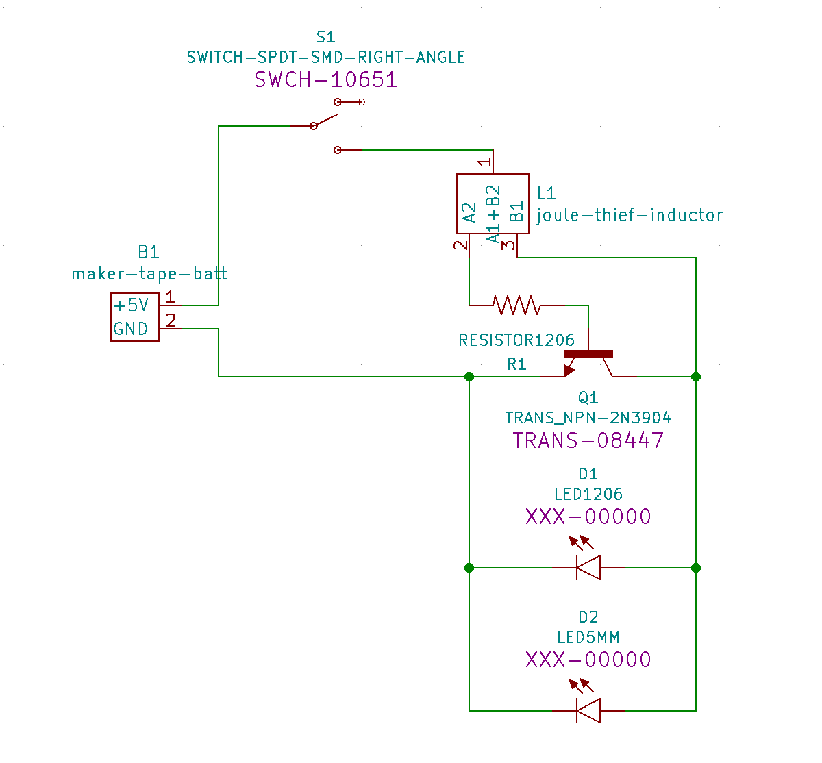
As you can see, you have a battery hooked up to an NPN transistor through a couple of oppositely-wound wire coils on a ferrite toroid (AKA ferrite core or bead). One of the windings goes from the battery's positive terminal (+) to the transistor's base, through a resistor. The other winding goes from (+) to the collector. But, note how the wires cross: the battery's (+) is connected to opposite ends of the two windings. This is important because, when power flows through the wires, it induces a magnetic field in the toroid. But it's going in opposite directions through each wire.
Our LED is connected between the transistor's collector and emitter legs. As yet, there isn't enough voltage to make it light up. Power is, however, flowing through the resistor, then through the base to the emitter of the transistor, just enough to start pushing open the pathway for power to flow from collector to emitter.
As this happens, a positive feedback loop begins, wherein the electricity flowing through the wires induces a magnetic field in the ferrite bead, as mentioned before. The magnetic field from this new pathway pushes more power through the base-connected coil, and the flow of electricity keeps feeding the magnetic field, until the toroid becomes saturated – meaning it essentially can't hold any more and the field starts to shut down – things are a little fuzzy here for me, but bear with me. 😅
So, when this happens, it stops the flow through the transistor and the magnetic field starts dumping its energy back into the electric coils, which shoves current through the oppositely-wound coil. This power is added in series to the trickle coming from the battery, it's sent to the collector and the LED's positive leg, and with the transistor closed up, all that sweet voltage courses through the LED at last, lighting it up brightly. (Big Clive's video shows the circuit dumping around 22.5V into a 9-chip series LED bar!!)
But the effect is short-lived, and soon it also decays, turning the lamp off and beginning the cycle anew. According to Clive (again), a normal frequency is around 80-100kHz, depending on the ferrite core you use and when it reaches saturation.
I made this PCB to make it easier to build your own Joule Thief! It will work with either AA or AAA batteries, in different orientations depending on your design, and for that reason, I didn't design it around a battery holder. Instead, there are big pours and slots in the PCB so that you can use Maker Tape (or other conductive tape) to connect it in various orientations – like the simple stand-up light seen above. There are also through-holes for wires to connect to battery holders, or whatever else you like. And, there's a power switch – because I hate hate hate having to disconnect batteries to turn things off! Particularly with expendable materials like Maker Tape, that can be such a drag.
I'm planning to design a variety of 3D-printed devices to run off these, so versatility is a must!
I laid out this version a bit weirdly, and might redesign it in the future so the two joined wire ends (which usually end up in the middle of the toroid) actually sit in the middle. The current layout confused me when I went to build it, weeks after ordering my boards, and led to DAYS of troubleshooting and worry! I finally figured out the issue when reconstructing the circuit on a breadboard. (In fairness, though, that's when I actually read the labels on the PCB... which would have cleared it up in an instant, ha.) The way it's currently laid out does make it very simple to see where the tracks lay, which will be helpful when I do the After Dark version.
The front is inspired by an emerald-cut jewel – in homage to the "Joule Thief" name – in a vaguely Art Deco style.
And of course, this PCB also works as an earring! :D
I try to make all my designs wearable, so that even if they don't work or I release a new update, they'll still have a cool purpose and stay out of the waste stream. Plus, tech jewelry is awesome, and FUNCTIONAL tech jewelry is the best!!! (I did in fact get my ears pierced as an adult, to have more ports for wearables...)
Salvaging ferrite coresThe most uncommon element in this circuit is the ferrite toroid (also called a ferrite bead or core). Unlike NPN transistors, 1Kohm resistors, or LEDs, these aren't usually part of a beginner's or hobbyist's kit. So, where do you get them – and what kind do you need?
I looked around on the internet and asked friends about this, and all seemed to say, "just grab one you have lying around!" or "any kind will do!" Well, this isn't such a great answer when you want to make a BUNCH of something and have it be repeatable! Here's what I found out, in the end:
Common sources
- Compact fluorescent light (CFL) bulbs
- Power transformers/adapters
Within these products, though, there's still variation. It took me a few tries to find the right kind of core in a transformer, because some use ferrite pieces that look like two E's stuck together (to make an "8" shape). It's possible those could work for this, but if so, I'm not sure how. And CFL bulbs are a bit dangerous to crack open – because of the glass, and because it's harder to get a grip on something you can break apart, since it's a fairly large-radius round object.
Eventually, I ended up at my local hackerspace, Noisebridge (woohoo!). On the "hack shelves", I finally found a big piece of loose circuitry with two LORGE ferrite toroids on it, plus another adapter/transformer that turned out to contain a couple more. Hooray!
Assembly and testingThe circuit is pretty well labeled on the board itself, but I'll put up an assembly video first. In my opinion, you should solder on the flat 1206 SMT resistor first, then the switch, the coil wires, the NPN transistor, and then the LED or other output.
Winding the toroid can be a little tricky. The next time I do it, I think I'll grab my hot-glue gun and put a dab on the starting point (with some length sticking out), to hold it in place while I wind the rest. The wire-wrapping wire works fine, but it doesn't quite stay where it's put. I managed to make it work by pinning it with my fingers and really cranking down the creases around the bead.
This video shows a test with my first prototype boards:
Short link to this project: https://bit.ly/hackjoule


Comments
Please log in or sign up to comment.