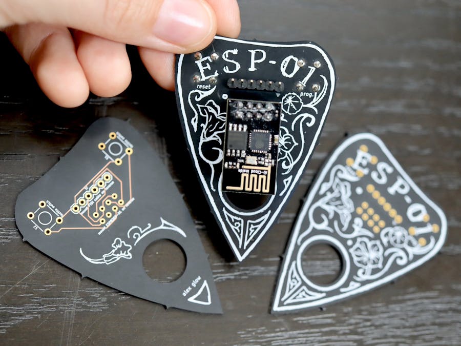
I'm building a suite of arcane tech tools that make everyday electronics tasks more beautiful. This one came out so nicely that the final version has a hole for an earring hook. (It's pretty large for an earring, but what a statement!)
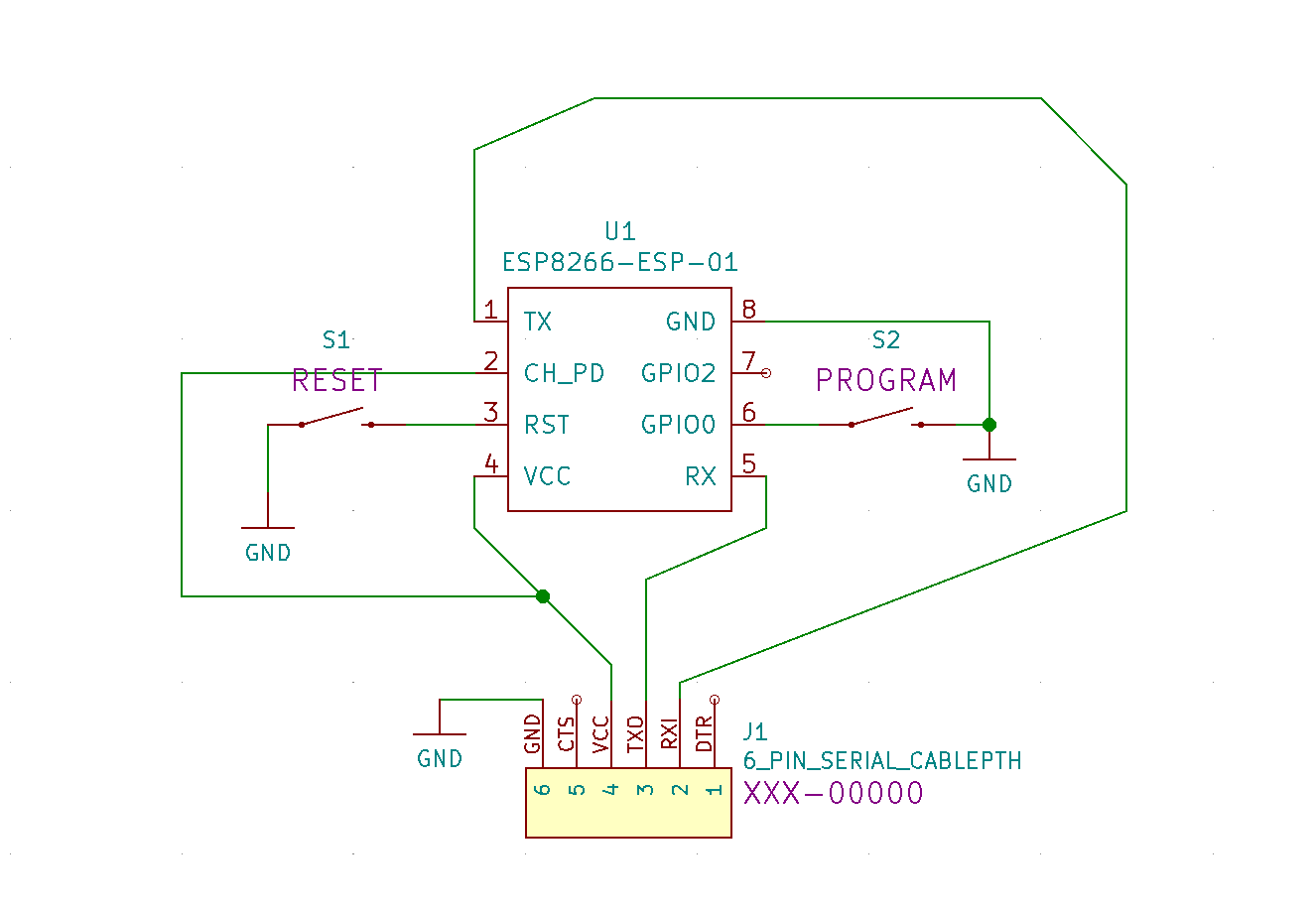
The original programming circuit came from this article by Alasdair Allan in Make. I've built a couple of ESP8266 programming jigs based on this in the past, and while they usually worked, sometimes there'd be issues attributable to loose wires, or other causes that would take ages to debug. So, when I decided to play with the ESP-01 module again, it was a no-brainer to design a PCB version.
Given the "ESP" naming of Espressif modules, I thought it'd be fun to make it in the shape of an Ouija-style talking board planchette.
Order now on OSH Park! Make sure to select the After Dark service, for maximum pretty. ✨
As mentioned above, the original circuit came from this article by Alasdair Allan in Make. I added buttons to make the programming/test process easier: to use it, press down both the Programming and Reset buttons, and then release Reset, then Prog. This will boot the board into programming mode. When it's time to test, just press Reset again and it'll boot into your sketch.
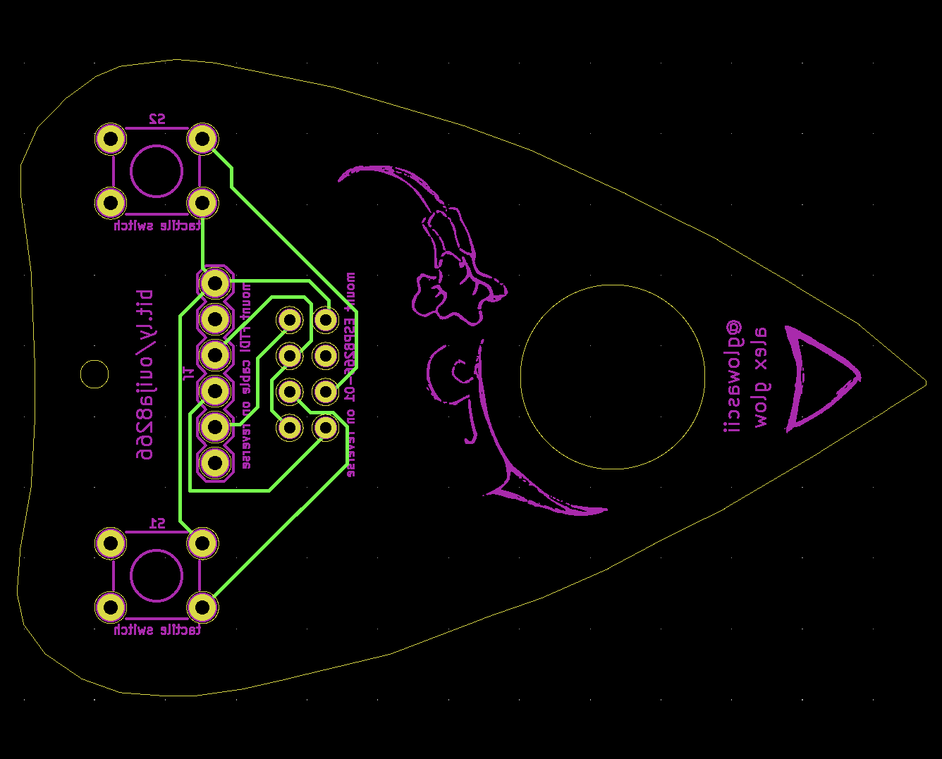
I designed these to be manufactured by OSH Park, whose "After Dark" service – clear solder mask and white silkscreen over black PCB substrate – makes a beautiful aesthetic statement. So, I did my best to place all of the wiring on the bottom of the board, since it shows through the solder mask. It isn't the most technically perfect, but it's pretty, and it works!
The buttons are placed on the bottom, so that the top design is unobstructed; they also act as standoffs for the board to rest on the desk, and provide a very satisfying action when you press down the corner of the planchette to program! I love little clicky buttons as much as anyone, but I love the solid feeling of using the board itself as the pressure surface.
I drew the top design in Procreate, on my iPad, using a rough brush that looks a bit like chalk drawing. The outline came first; I determined the dimensions from an image of a standard planchette, and used that to create the outline of the PCB in KiCad. Afterwards, I ended up making a second, cleaner version that blended better with the overall aesthetic. I kept the outline and center circle on their own layer, so I could independently edit the top and bottom design elements and play around with ideas.
For the plant designs, I took inspiration from these Art Nouveau-esque nasturtiums in a public-domain image by Maurice Pillard Verneuil. I traced a couple of the flowers and placed them around the planchette, with my own added curlicues and flourishes.
I used a standard serif font to create and place the ESP-01 lettering, then traced it and added a bit of extra character with the lining. In my opinion, the silkscreening on this looks spectacular; a beautiful job by OSH Park!
There are other useful bits of text and images, here and there: a ground indicator to show you which way the FTDI cable goes on, text labels telling you how to solder on the headers, and "reset" and "prog." labels for the buttons. Labels are important, but they don't have to mess up your aesthetic ;)
UsageI ran a test using the same Arduino example code as my previous jig (reproduced in the Code section below).
- Install the ESP8266 board definitions through Tools > Board > Boards Manager, and select "Generic ESP8266 Module"
- Grab this Arduino sketch: Examples > ESP8266 WiFi > WiFiManualWebServer
- Put in your WiFi SSID + password (if applicable)
- Select an LED_BUILTIN pin in the Tools dropdown – this may vary between generations of ESP8266-01, and there's a note about it in "Troubleshooting" below!
- Reset the board into programming mode: Press down on both the RESET and PROG buttons. Release RESET, then release PROG.
- Upload the sketch
It works!! 💙
I mean, the words "on" and "off" are backwards... but that's an easy fix. :)
Can't wait to use this for some real projects!
TroubleshootingConstantly resetting: Solder a 0.1uF capacitor between the VCC and GND pins. This was an oversight on my part – the decoupling capacitor will be built into future versions of the board! If that doesn't fix it, here are some other tips you can check.
LED pin: You may need to try different LED_BUILTIN pins, depending on the generation. I had mixed results with using the dropdown menu, but typing in the pin number in the sketch itself worked well. (I spent AGES trying to get that LED to respond, only to find that my older models have it on pin 1, whereas newer ones may have it on pin 2.)
Updates- Current version: added hole for use as earrings / pendant / key fob / etc.; added Hackster logo to back.
- Next version: add spot for optional capacitor


_4YUDWziWQ8.png?auto=compress%2Cformat&w=48&h=48&fit=fill&bg=ffffff)


_Ujn5WoVOOu.png?auto=compress%2Cformat&w=40&h=40&fit=fillmax&bg=fff&dpr=2)


Comments