


Hardware components | ||||||
| × | 1 | ||||
 |
| × | 1 | |||
 |
| × | 1 | |||
 |
| × | 1 | |||
 |
| × | 1 | |||
 |
| × | 1 | |||
 |
| × | 1 | |||
| × | 1 | ||||
| × | 1 | ||||
| × | 1 | ||||
Software apps and online services | ||||||
| ||||||
| ||||||
| ||||||
Hand tools and fabrication machines | ||||||
 |
| |||||
 |
| |||||
In this project I outline how I made a custom LED neon sign out of recycled components to give as a gift!
The letters in the middle of the neon sign can flash with an adjustable frequency or be set to run constantly (controlled by the knob on the front). The power switch on the side turns the sign on or off. The sign is powered by a recycled 12V DC power supply I found at a recycling coop.
Mechanical DesignMy inspiration for this neon sign was recycling a broken neon sign I picked up for $2 at a garage sale.
The first thing I did was remove the LED strips. I did this by pulling it off where possible and using a utility knife to separate the glue from the strips.
After removing the LED strips I measured what length of each strip I had. These LED strips have cutting points every inch so each section of strip had to be divisible by one inch.
I decided to use the vector graphics software "Inkscape" for my initial design so I could use up as much of the LED strip length as possible and also export the design easily into Fusion360 for 3D modelling.
Each segment of LED filament was represented as a separate path in my file. I used the inkscape extension "Visualize Path" to measure the length of the paths and ensure they were divisible by an inch and that all the filament was used. In the end I used all of the LED strips except for 2 inches.
Once I was happy with my design I imported it directly into Fusion360 as an SVG. In Inkscape I used the stroke feature to better visualize the thickness of the LED strips but the paths were imported in Fusion as a thin path line.
When importing.svg files from Inkscape into Fusion360 the scale is not preserved. In Fusion360 I first scaled up imported paths to make sure they matched the inkscape dimensions. Take care to make sure the size is correct in Fusion if you're creating your own design!
Using the imported paths as a base I made a sketch in Fusion for the LED strip channels and sign shape. I made sure to measure the width of the strips (5mm) and make the channels slightly wider (0.25-0.5mm).
Using the sketch as a base I modelled the rest of the sign. I added three screw keyhole mounts on the back to attach the sign to a wall. I made sure to add holes to route the wires from each LED strip to the electronics enclosure. I also added some bolt holes and alignment tabs so I could install the Digikey project box on the bottom.
I measured and modelled the project box in Fusion. I measured the potentiometer shaft and created a knob that would friction fit over top.
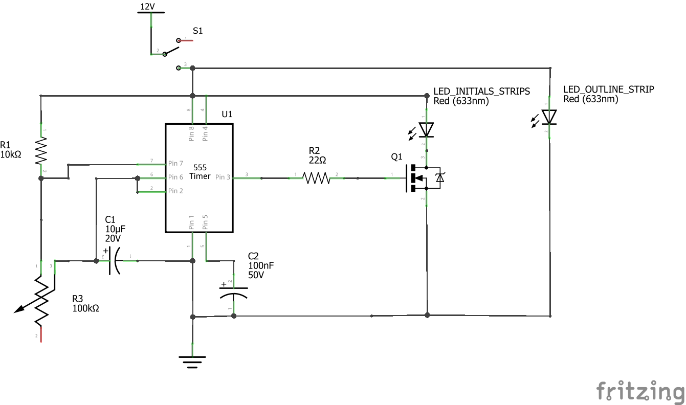
The electronics behind this sign are a 555 timer astable multivibrator circuit with a MOSFET on the output to drive the LED strips.
I created a schematic and breadboard layout in Fritzing.
I implemented the circuit on a solderless breadboard and adjusted the values with the components I had on-hand until I reached the desired frequency range of the flashing circuit.
I also took the opportunity to test how much current the LED strips would draw to make sure the components were sufficient and to choose a power supply. In total my strips draw about 1.5 amps. Luckily I had a 12V, 3A power supply on hand that I got from a recycling coop.
The first part of assembly was 3D printing the sign and the knob. I printed the knob with no raft or support material. I 3D printed the sign with no raft and limited supports for a few overhangs.
After 3D printing I cut the LED strips into the appropriate length and soldered 22 gauge stranded wire to the power inputs. I inserted the strips into the sign and used hot glue to cover the solder joints and prevent accidental shorts.
I prepared the project box by cutting holes for the wires, potentiometer, and bolts. I also filed out a square hole to fit my switch. All holes in the enclosure were made using a drill and a set of files.
I transferred the breadboard design from my solderless breadboard to the PCB breadboard and soldered in the components. I had to cut down part of the PCB breadboard to fit around the machine screws connecting the enclosure to the sign.
After soldering I briefly tested the circuit with all the components. Everything was working so I started to fully assemble the sign.
To finish up I sealed the electronics enclosure. I also re-printed the knob because the colour change didn't work properly on the first one. And with that the sign was complete!

Comments
Please log in or sign up to comment.