


Hardware components | ||||||
| × | 1 | ||||
| × | 1 | ||||
| × | 1 | ||||
| × | 1 | ||||
| × | 1 | ||||
| × | 1 | ||||
Software apps and online services | ||||||
 |
| |||||
Hand tools and fabrication machines | ||||||
 |
| |||||
 |
| |||||
For this project I wanted to create a light-up flower crown with the electronics integrated seamlessly into the crown.
This post showcases the flower crown and includes some partial instructions. Some of the parts (ie the RGB flower) are discontinued but you could easily find or make a replacement to re-create this project :)
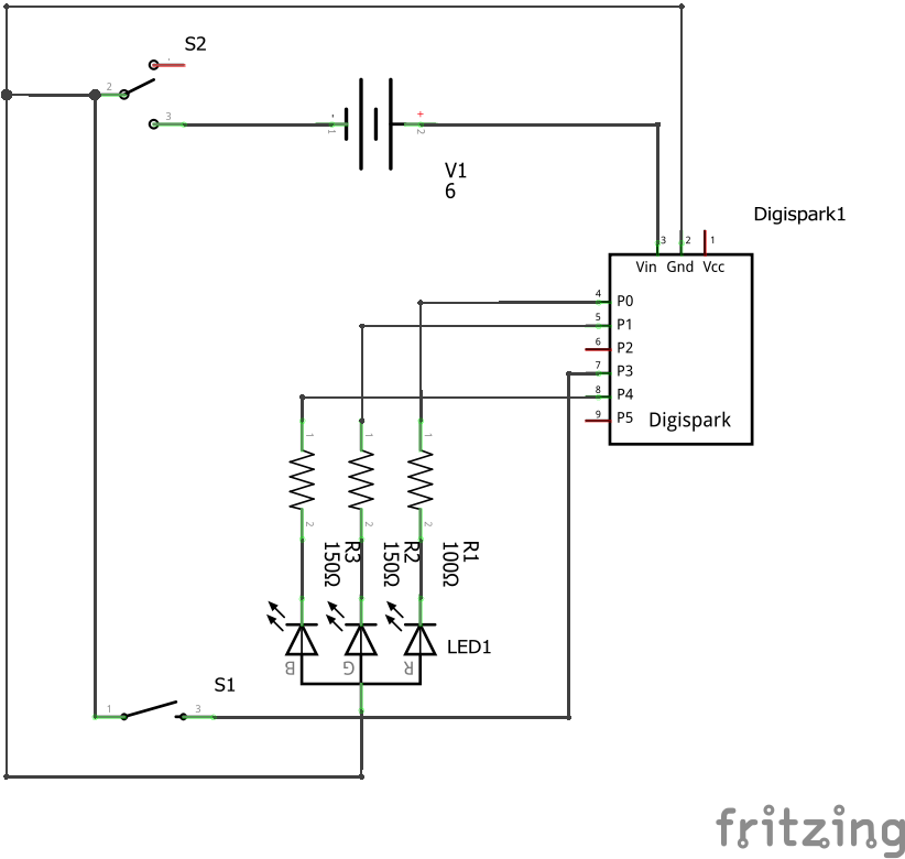
Most of the electronics in the flower crown are hidden behind the flower except for the battery pack which is camouflaged on the back of the crown. The flower crown has two switches: One power switch on the electronics enclosure and one mode switch embedded into the band. The mode switch is used to cycle through four solid colour modes and three pulsing modes.
The flower crown runs on two CR2032 coin cell batteries. The electronics box has four sockets for the leads of the RGB flower so it can be replaced. There is also a microUSB available on the side of the enclosure for reprogramming the flower crown.
To assemble this project we started off by finding a collection of fake plants and paper flowers with wires so we could form the basic flower crown. We used a fake ivy strand as the base and affixed the paper flowers to the ivy. We also added some thin gold wire to add an accent to the crown.
The enclosure and lid were 3D printed at the same time. Stranded core wire was soldered to all the required connections on the microcontroller board. Extra long green wires were used for the battery pack and mode switch connections since these were going to be mounted outside the enclosure along the crown. The resistors were also soldered directly to the relevant GPIO. See the schematic for details.
The microcontroller was then hot glued into place at the bottom of the enclosure with the USB sticking out the side. The switch was installed with the a ground wire from the battery pack on one pin and the ground connections to the other parts of the circuit on the other pin. The switch didn't fit perfectly so it was installed on a slight angle and hot glued in place.
Originally I was going to install the flower on top of the enclosure but after 3D printing it I decided to install it on the front instead. I used a drill and exacto knife to cut out an extra slot in the enclosure and install some headers for the LED pins.
The digispark board has a USB connector, but it is wired directly to the microcontroller instead of going to and USB programmer. Because of this simple hardware design, the microcontroller has a bootloader installed on it which emulates USB and is active in programming mode for 5 seconds after power up.
The board can be programmed through the arduino IDE, but it is a slightly different process then a normal arduino board and requires some extra drivers.
You can find the details about how to install the drivers and program a digispark board on the official wiki: https://digistump.com/wiki/digispark/tutorials/connecting
Note: When programming the flower crown, the power switch should be OFF. The USB will provide power while programming.


_3u05Tpwasz.png?auto=compress%2Cformat&w=40&h=40&fit=fillmax&bg=fff&dpr=2)


Comments