
Hardware components | ||||||
| × | 1 | ||||
| × | 1 | ||||
 |
| × | 1 | |||
Many radio devices such as GPS, mobile phones and radio controlled drones use spread spectrum techniques to drastically improve the signal to noise ratio, prevent jamming and other stuff. You can use the same technique with audio. I'm using this technique to hide a message in a ring tone. A device pretending to be a keyboard would detect this and print "spooky" on an attached computer.
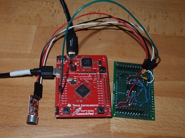
The system consists a phone that plays the ringtone and a TIVA C LaunchPad that should be hidden behind a computer but connected to it via USB.
It is really quite interesting to both create a working system and also make one work with audio. Anyway, if you are interested in DSS radio, but don't or can't work in high radio frequencies, read on.
This one has a center frequency of just 1KHz and a bandwidth of 1KHz (500 Hz either side of 1KHz. The effective baud rate is just 1 baud.
Of course there are probably more useful applications such as underwater or firefighting communications (smoke blocks radio signals sometimes). It can also be used as a good sonar "ping" rather than a standard "chirp".
Challenges
Before coding anything on the TIVA C LaunchPad, it is better to simulate everything on a PC because it is easier to debug, plot and you can use floating point numbers. I used C++ and Intel's performance primitives, just because I know them best, but it would be better to use MATLAB or Mathematica. You can also copy and paste data from the TIVA C LaunchPad to the PC to see exactly what is happening.
Integers and not floating point numbers were used on the TIVA C LaunchPad for performance. But really, it only needed to do 5 FFTs every 2 seconds, so there was not a huge load on the CPU.
The digital filter was designed using http://t-filter.engineerjs.com/
The analogue filter was designed using information from Texas Instruments' "A Single Supply Op-Amp Circuit Collection".
There is a lot of theory behind spread spectrum, this is really just a practical application of it. It is interesting to take stuff from theory and go through the process of implementing it.
m-sequences
The first step is to create m-sequences (just a series of pseudo-random -1s and 1s) that represent different symbols in a message. In this project, four are used and they are named 'A', 'B, 'C' and 'D'.
The ones chosen were 1023 bits long because I found source code from the web that could do 1024 point FFTs on the TIVA C LaunchPad. This will be explained later. Since I was using four symbols, four unique m-sequences were generated. Each sequence consumes 4096 bytes, so you can't have too many without running out of room on the TIVA C LaunchPad.
Code from a MATLAB file (mseq.m by (c) Giedrius T. Buracas, SNL-B, Salk Institute) was adapted to C code to generate sequences. The top waveform in the picture below is one of the m-sequences. m-sequences have the property that they don't correlate well with each other and they do correlate well when they are exactly in phase.
Converting a 1023 bit sequence into 1024 bit
My initial experiment was not to worry too much about spreading the 1023 bits to 1024. And it worked ok, but obviously not as well as it could. Initially the signal was just linearly interpolated, but that was worse than not spreading at all. Then I tried up-sampling by 1024 and then down-sampling by 1023. That was even worse than linear interpolation! Then it struck me: put the signal into the complex domain and add the real and imaginary components to form a signal for the ringtone. I'm not 100% sure about this, but it works :)
Modulation
The next step is to modulate the signal. I wanted to limit the bandwidth so I needed to interpolate before this step. There are many ways to interpolate, but a frequency friendly one is to add zeros and perform a low pass digital filter. I added seven zeros after every bit in the sequence and then passed a 145 point low pass digital filter over it. This digital filter had a band pass between 0 and 450 Hz and band stop between 500 and 2000 Hz. The sine wave I multiplied the signal against to modulate was just a repeating sequence of 1, 0, -1, 0. This shifted everything up by 1000 Hz. The diagram below shows the m-sequence being modulated and de-modulated.
You can see the spectrum of a raw m-sequence below, it is trying to be a box and maximizes bandwidth utilization. The diagram below that is the same signal except it has been interpolated and frequency shifted up to 1 kHz (as described above).
Ringtone
The next step is to superimpose the signal onto a ringtone.
The following is the ringtone (as heard in the video) with the hidden message (bottom wave form). You can see how small it is and this is to be picked up by a 12 bit analogue converter. The hidden message by itself sounds like the noise from a computer fan.
Analogue Front End
The analogue front end just consisted of an active low pass filter that aimed to pass below the 2 kHz range. It is just a filter from one of Texas Instruments' notes with a 10uF decoupling cap between it and the microphone.
Originally I was making my way through creating a non-inverting filter, but after a few wiring errors, I ended up adapting it to be an inverting one.
The analogue signal was passed straight into a 12 bit analogue to digital converter on the TivaC Launchpad.
Processing on the TIVA C LaunchPad
The first thing the TIVA C LaunchPad does is to demodulate and filter.
Demodulation is simply multiplying the signal by the carrier to bring it back to zero Hz and into a complex signal (real and imaginary components). If you can imagine a sine wave that takes the form 1,-1,1,-1,.. etc. if you multiply it by itself (another sine wave: it will bring it back to DC), ie 1*1, -1*-1, 1*1, -1*-1,... etc = 1, 1, 1, 1 - a DC signal.
Then I also needed to digitally filter the result to get rid of everything over 500 Hz. You can see the results of demodulation in one of the earlier diagrams.
Correlation
The interesting bit is the frequency correlation. What you do is perform a FFT on the model (signal reversed) and complex multiply it against the FFT of the incoming observed signal. Then you do an inverse FFT on that and out should pop a correlation...
This correlation is done against all the symbols to find the best fit. To confirm one symbol was received, the correlation needed to be 4 times larger than the correlation of any of the other symbols.
The correlation is used to phase sync the FFT (1024 sample) window. To do this phase sync, I actually repeated the first symbol in the message.
An uncorrelated graph looks like this:
The Message
The message I was looking for to trigger the TIVA C LaunchPad (pretending to be a USB keyboard) was just symbol 'A' followed by symbol 'B' and that takes 4 seconds to send. The actual message in the ring tone was 'A' 'A' 'B' with the first 'A' used to phase sync as described above.
USB keyboard
The demo code from Texas Instruments was used to create the keyboard. It is really simple to use. It creates a standard keyboard so no drivers are required to be installed on the PC.
Upon reception of the secret 'A', 'B' message, the TIVA C LaunchPad (pretending to be a USB keyboard) acted as if the message "spooky" was typed.
The LEDs were also flashed to indicate the reception of the different symbols.
Surprised it worked
I'm actually surprised it works so well. In fact, unless you are listening hard and know what you are listening for, you probably would not notice. It would just sound like the hum of a fan.
Below are the graphs of the data from the TIVA C LaunchPad. The first is just the symbol 'A' being transmitted, the other with it hidden in the ring tone. The large numbers on the left vertical axis are due to the calculations being done in fixed point numbers.
You can see the ring tone creates a lot of background noise so the peak is probably 7dB above the noise. When processing just the symbol, it is closer 20dB. In theory it should be more like 30dB (3*log2(1023)), but that is theory.


Comments