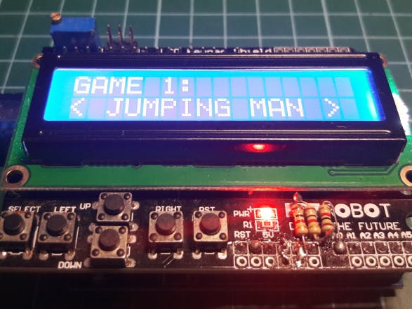
Recently, I have bought an LCD Keypad Shield for Arduino. It cost about 3$ and I have some “fun” with it for a whole week. It works just fine with the example codes, but some features might be missing like the interrupt function in some other digital pins.
Why is interrupt function while working with buttons so important? Maybe with a small and basic program, the example can handle those buttons pretty well. But with a much bigger and more complicated program like a game perhaps, interrupt function is crucial if your goal is to make a program that can work in real time.
First, we need to know how this keypad works by looking through its schematic. Basically, all of the buttons are connected to pin A0 on the Arduino Uno. The board distinct each button by their analog value from 0 to 1023 (0 to 5V). For the right button, the analog value is 0 since there is no resistor between it and pin A0. Therefore, the electric current will just go straight to the ground without running to pin A0. For other buttons, the analog value can be calculated with the voltage divider formula. To illustrate this, let’s calculate the analog value of button up.
But after experiencing with this keypad for a while, I found out that the value of the resistor connected to left button and select button of my keypad is not that correct. This could be a technical issue with the manufacturer.
With Arduino Uno, only digital pin 2 and 3 are supported with the normal interrupt (attachInterrupt). This leads to another problem which is there is no way of using the normal interrupt on pin A0. Therefore, we can only address this issue by using another interrupt called “Pin Change Interrupt”. So basically, this interrupt kicks off when the state of the pin changes from High to Low (or the other way around) depends on how you config your analog pin (pull-up/ pull-down). With the schematic of the keypad, it is obvious that pin A0 is pulled up. This means that only signal at Low-level voltage can trigger the Pin Change Interrupt on this pin. You can see more about the voltage level from this page:
https://www.arduino.cc/reference/en/language/variables/constants/constants/
But what I encountered with is the voltage that triggers the state change of pin A0 is around 2.5V. (I do not have a multimeter for this but with 4 tests, I could narrow down the value from 480 to 520 which is around 2.5V). What you need to do now is just adding a resistor to your pin A0 and connect it to the ground. The value of the resistor is depended on how low you want to set your select button analog value without make pin A0 pull-low.
In my case, after soldering a 3k resistor (technically, it is the combination of 3 1kOhm resistors), I can only make the left button work since the analog value of the select button is too high to be considered as a low state and trigger the Pin Change Interrupt. Of course, it is possible to fix this issue by replacing the 5th resistor on the board with a resistor that fits my calculation, or I can just use a potentiometer. But since I’m not very good at de-soldering and I also do not have any potentiometer lying around, I will accept the loss of the select button and use the up button to select instead. After changing the analog value of those buttons, you should go to the ButtonCheck(uint16_t adc_value) in the Interrupt file and change the value of each button.
There are two simple games in this application of the LCD Keypad.
The first one is called Jumping Man which is created by Iron_Salsa using the normal interrupt on digital pin 2. In this case, I only need to use Pin Change Interrupt to make this game work well on the LCD Keypad Shield.
Link to Iron_Salsa project:
The second one is called Pacman which is created by… using the LCD Keypad Shield examples. There is nothing to talk about this game except it is a pretty good game to play on and 16×2 LCD.
That’s it for my tutorial about the LCD Keypad Shield. More tutorials will come in the future.
The full source code of this project: https://github.com/dtnghia2206/LCD_Shield


_ztBMuBhMHo.jpg?auto=compress%2Cformat&w=48&h=48&fit=fill&bg=ffffff)


Comments
Please log in or sign up to comment.