At the core of any time-lapse camera rig is the controller – an “intervalometer” – but what all but the most expensive ones lack is the ability to configure a shooting schedule based on the time of day and day of week.
And so it is that the “Intervalometerator” came into being. It’s the intervalometer’s intervalometer, hence the convoluted name we were quick to abbreviate to “intvlm8r."
By providing some free labour and with a good-quality second-hand DSLR from eBay or similar, you should be able to build an Intervalometerator for around USD $800.
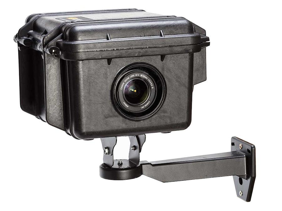
What Is It?A completed "intvlm8r" is a Pelican case with a DSLR camera, lens, a control PCB, and a power source, bolted to something stable. As presented here it's suggested you'll want a solar panel, solar charger and a small-ish SLA battery, but those are unnecessary if you have mains power.
At its heart are two micro-controllers, each serving a specific purpose. An Arduino Pro Mini is the master, with a battery-backed external real-time clock signalling it to wake the camera and fire the shutter. These are the two critical components to the Intervalometerator. The Arduino normally spends its time asleep when it’s not triggering the camera to take photos, and while snoozing the entire rig pulls almost zero current from its battery power supply.
A Raspberry Pi Zero W provides a web-based “front-end” where all configuration and management takes place. An I2C bus between the micros handles the higher-level communication, while 3 digital IO lines between them provide ‘wake’ and ‘shutdown’ signalling. The digital IO reduces the risk of drive corruption as the power-hungry Pi’s power is applied and removed under the Arduino’s control – where the Pi’s left to sleep as much as possible. (In case you’re wondering, we couldn’t implement this in I2C as the Arduino can only slave to the Pi – it’s unable to initiate a command.)
Why?Some friends of ours have fled Australia to build their dream home in rural New Zealand, about an hour's drive from Wellington at the southern end of the north island.
The site is TOTALLY off-grid and devoid of anything resembling network connectivity. The only thing they can rely on there is sunshine. When it's not raining.
Wisely or otherwise, we thought that a time-lapse movie of the building of said home would make a great housewarming present, and so a not inexpensive rig based on a GoPro was procured, tested, personally delivered to New Zealand and installed.
After its first images were received and processed, we decided we weren't happy with the video quality out of the GoPro, and that a DSLR would capture a better image. The only problem is that comparable rigs cost MANY thousands of dollars – and that’s before you add the camera and lens.
"It can't be that hard. Why don't we just build one?" - and so commenced our unexpected 12 month quest.
ConceptThe project took just on 12 months to take from concept to final PCB. It evolved from a high-level whiteboard concept drawing...
Through a hand-scratched circuit...
... and eventually to a proper circuit and PCB:
Camera ControlThe basics of the camera interfacing all happens over the camera's 3-wire manual shutter release. The Arduino, having been woken by the clock, electrically "half-presses" the shutter button (the "Wake" opto on the board), pauses, then lights up the "Fire" opto, triggering the photo. Both signals are reset, the Arduino sets the next alarm time and goes back to sleep.
Advanced camera control takes place over USB via the Raspberry Pi. The power-hungry Pi is usually turned off, woken on a daily schedule to copy images off the camera and for any routine maintenance the operator may require. An option exists in the code for it to run permanently if you have a mains-powered setup. A reed switch from a burglar alarm mounted inside the box lets someone on-site wake the Pi by waving a magnet near it, without needing to break the weather seal on the Pelican case or risk bumping the camera out of alignment.
It's worth noting at this point that the Pi isn't critical to the primary function of the Intervalometerator: when the Pi is off - or should it be dead for whatever reason - the camera will still take photos on the pre-configured schedule.
The project couldn't have gotten off the ground if it weren't for two open-source projects, and we remain totally indebted to their contributors. The Pi code is totally reliant on and derived from both the gPhoto2 project, and python-gphoto2, Jim Easterbrook's Python interface to same.
The WebsiteIts website is fairly basic, but across a handful of pages you're able to view and download the captured images, check camera and timing settings, check thermal measurements and other system setup tasks.
There's a live demo website running in Azure. It’s been modified a little for Azure and creates cookies on your machine to fake the interaction with a non-existent camera, but the end result is an otherwise true rendering of the site. The photos on the home and thumbnails pages are of the Sydney CBD, taken while the first unit was on our roof for testing in late 2018.
Off-Board PartsAll of the PCB-mounted items are listed in the "Things" list above. In addition to those you'll want:
- A camera. We found a Canon 60D and 600D on eBay for very favourable prices. Look for those with a low shutter count, and avoid those where it's not mentioned in the listing.
- A lens. eBay again delivered quite economically.
- For the camera you'll want an appropriate battery adapter (aka a 'fake battery') and a manual release cable.
- A case. We went with a Pelican 1300.
- To mount the camera inside the case we used a Manfrotto Rapid Connect Adapter with 357PLV Camera Plate.
- The lens hole in the side of the case is sealed with a 77-82mm filter step-up ring, to which your choice of an ND or UV filter is attached.
- The cable to your solar cell or power supply needs to route through a cable entry gland to ensure the box remains sealed to the weather.
- A mount to affix the Pelican case to a pole/etc.
- If not mains-powered, a solar cell, SLA battery, and charger. These are the ones we used in the finished product.
Snap-HappyOur first production unit has been running in New Zealand since January 2019.
Thankfully – from a product development perspective – it hasn’t been an entirely smooth ride. First the relatively new SD card died, but we were able to have that replaced by our mates on-site, saving us the emergency trip to NZ. The issue was documented and extra traps added in the code for this particular failure scenario. Reinstating the intvlm8r after memory card surgery then (eventually) revealed that the cable to the solar panel requires a bit of extra muscle to make a connection. Failing the application of said muscle means the battery won’t charge and will eventually go flat. Noted for next time.
Whilst it’s currently snapping 4 photos an hour for 12 hours a day (Monday-Friday), there’s not actually any movement on site beyond the odd grazing sheep. Delays with finance, architects and builders have reached Grand Designs (NZ) proportions, but we’re assured of some photo-worthy opportunities commencing #RealSoonNow.
It could yet be another year before this whole thing is wrapped up and we have a housewarming video to show for it, but we’re confident and remain enthusiastic.
More infoAll the code is on GitHub, as well as detailed build instructions, a full shopping list, troubleshooting and much more explanatory text. The PCB for it is on eBay.


_3u05Tpwasz.png?auto=compress%2Cformat&w=40&h=40&fit=fillmax&bg=fff&dpr=2)
Comments