I once worked in a company that sells health-care devices and I've knowledge of how blood pressure monitors work. In this project I will use a micro pressure sensor to detect Korotkoff sounds, which will help me to calculate systolic (maximum) and diastolic (minimum) blood pressure. There is another method called the oscillometric and I will not use it because I don't have enough hardware and time to finish it. However the oscillometric method is based on the Korotkoff sounds and each manufacturer develops its own mathematical algorithm to find systolic and diastolic pressures. Reference: https://www.nature.com/articles/s41371-019-0196-9
I can tell you that the project that was made with GNAT Programming Studio is my own and my creativity (source code, schematic diagram and flowchart). For the rest, I used and modified the arduino demo code from the pressure sensor manufacturer, and the code to send the test data to excel. Let's get started with the list of necessary hardware.
Korotkoff sounds are the sounds that medical personnel listen for when they are taking blood pressure using a non-invasive procedure. They're named after Dr. Nikolai Korotkoff, a Russian physician who discovered them in 1905, when he was working at the Imperial Medical Academy in St. Petersburg, Russian.
If the cuff of a sphygmomanometer is placed around a patient's upper arm and inflated to a pressure above the patient's systolic blood pressure, there will be no sound audible. This is because the pressure in the cuff is high enough such that it completely occludes the blood flow.
If the pressure is dropped to a level equal to that of the patient's systolic blood pressure, the first Korotkoff sound will be heard. As the pressure in the cuff is the same as the pressure produced by the heart, some blood will be able to pass through the upper arm when the pressure in the artery rises during systole. This blood flows in spurts as the pressure in the artery rises above the pressure in the cuff and then drops back down beyond the cuffed region, resulting in turbulence that produces an audible sound.
Eventually, as the pressure in the cuff drops further, the sounds change in quality, then become muted, and finally disappear altogether. This occurs because, as the pressure in the cuff drops below the diastolic blood pressure.
There're five Korotkoff sounds:
- Phase I—The first appearance of faint, repetitive, clear tapping sounds which gradually increase in intensity for at least two consecutive beats is the systolic blood pressure.
- Phase II—A brief period may follow during which the sounds soften and acquire a swishing quality.
- Phase III—The return of sharper sounds, which become crisper to regain, or even exceed, the intensity of phase I sounds.
- Phase IV—The distinct abrupt muffling of sounds, which become soft and blowing in quality.
- Phase V—The point at which all sounds finally disappear completely is the diastolic pressure.
Traditionally, the systolic blood pressure is taken to be the pressure at which the first Korotkoff sound is first heard and the diastolic blood pressure is the pressure at which the fourth Korotkoff sound is just barely audible. However, there has recently been a move towards the use of the fifth Korotkoff sound.
Reference: https://en.wikipedia.org/wiki/Korotkoff_sounds
The SparkFun Qwiic MicroPressure Sensor is a miniature breakout equipped with Honeywell's 25 psi piezoresistive silicon pressure sensor. This MicroPressure Sensor offers a calibrated and compensated pressure sensing range of 60 mbar to 2.5 bar, easy to read 24 bit digital I2C output.
Each Qwiic MicroPressure Sensor has a calibrated pressure sensing range from 1 - 25 psi (52 - 1293 mmHg) and a power consumption rate as low as 0.01 mW typ. average power, 1 Hz measurement frequency for ultimate portability. Used in multiple medical (blood pressure monitoring, negative pressure wound therapy), industrial (air braking systems, gas and water meters), and consumer uses (coffee machines, humidifiers, air beds, washing machines, dishwashers).
Reference: https://www.sparkfun.com/products/16476
I bought this sensor two months ago, the libraries are made to work in the Arduino IDE. So I used the demo example and modified it to convert the pressure data into mmHg, remove the atmospheric pressure component, and send the data to the output of the DAC_1 (analog digital converter), on pin D25 of the ESP32-WROOM-32 board every 200 ms.
There're 2 channel 8 bit DACs in the ESP32 to convert the digital signals into analog voltage signal outputs. So value 1 corresponds to 11.76 mV, value 2 corresponds to 23.53 mV ... and value 255 corresponds to 3000 mV. You can download the code in the download section as pressure_sensor.ino.
#include<Wire.h>
#include <SparkFun_MicroPressure.h>
SparkFun_MicroPressure mpr; // Use default values with reset and EOC pins unused

#define DAC2 26

float min_pressure = 600;

void setup() {
  // Initalize UART, I2C bus, and connect to the micropressure sensor
  Serial.begin(9600);
  Wire.begin();
  if(!mpr.begin())
  {
    Serial.println("Cannot connect to MicroPressure sensor.");
    while(1);
  }
}

void loop() {
  float sensor_pressure = (mpr.readPressure(INHG)*25.4);

  if(sensor_pressure<min_pressure){
      Serial.println("new minimum pressure");
     min_pressure=sensor_pressure;
  }

  sensor_pressure = (mpr.readPressure(INHG)*25.4);
  int pressure_total = sensor_pressure - min_pressure;

  dacWrite(DAC2, pressure_total);
  Serial.print(pressure_total);
  Serial.println(";");
  delay(200);
}The STM32F429I board was programmed with GNAT Programming Studio 19.1 Developed by AdaCore. This part develops the most important control function of the system and I will detail below. The schematic diagram and the flowchart you can get at the end of this tutorial. As a reference for this project, I've used the following Ada tools:
- 1) examples such as demo_adc_polling, and demo_gpio_direct_leds;
- 2) Ada drivers libraries like STM32.User_Button, STM32.ADC, STM32.GPIO, and LCD_Std_Out; and
- 3) Theory sucha as arrays, and for and while loops.
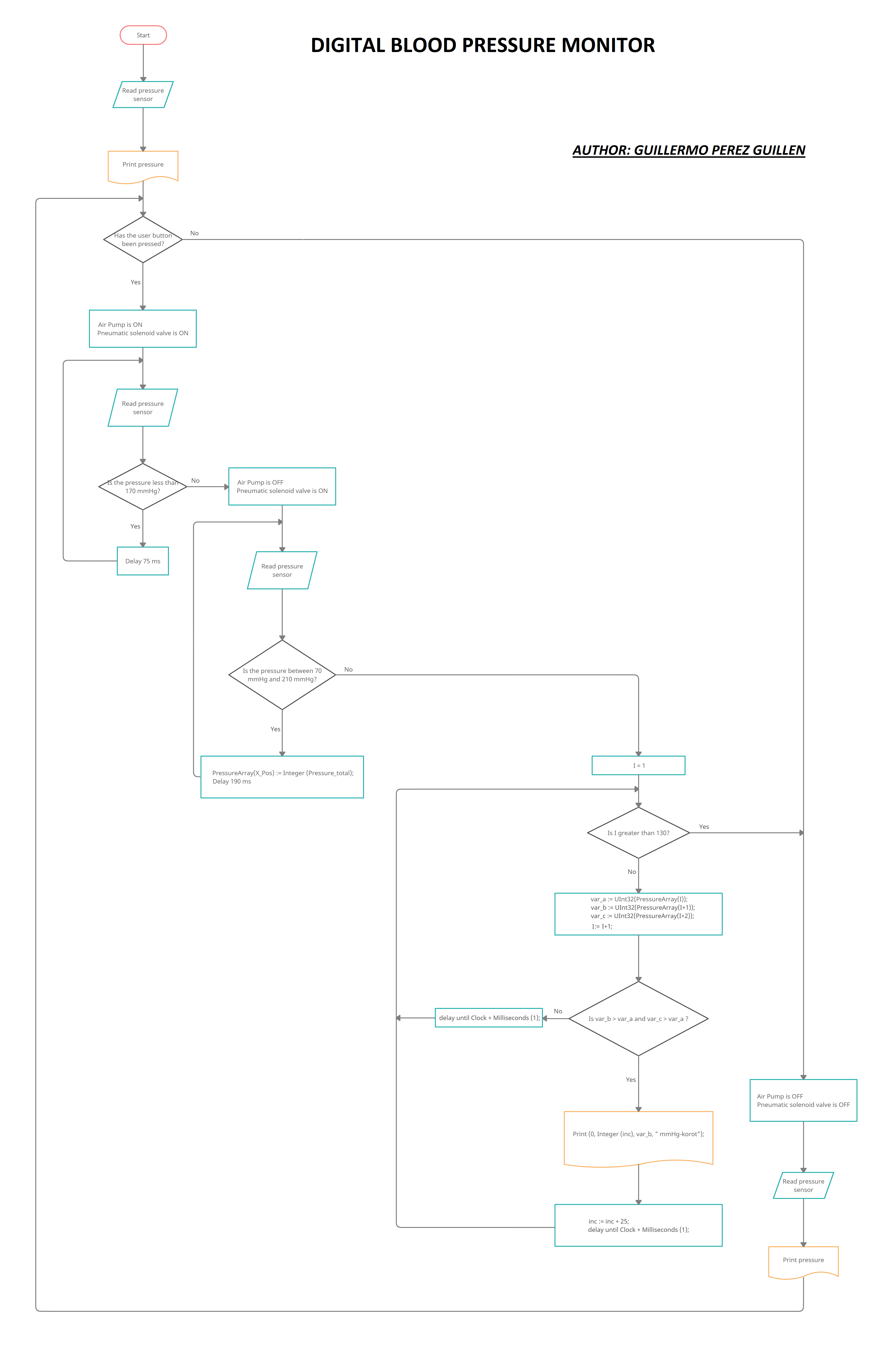
The analysis of the code of the digital blood pressure monitor I've divided it into three sections:
- Inflation of the cuff,
- Deflation of the cuff, and
- Calculation of the Korotkoff sounds.
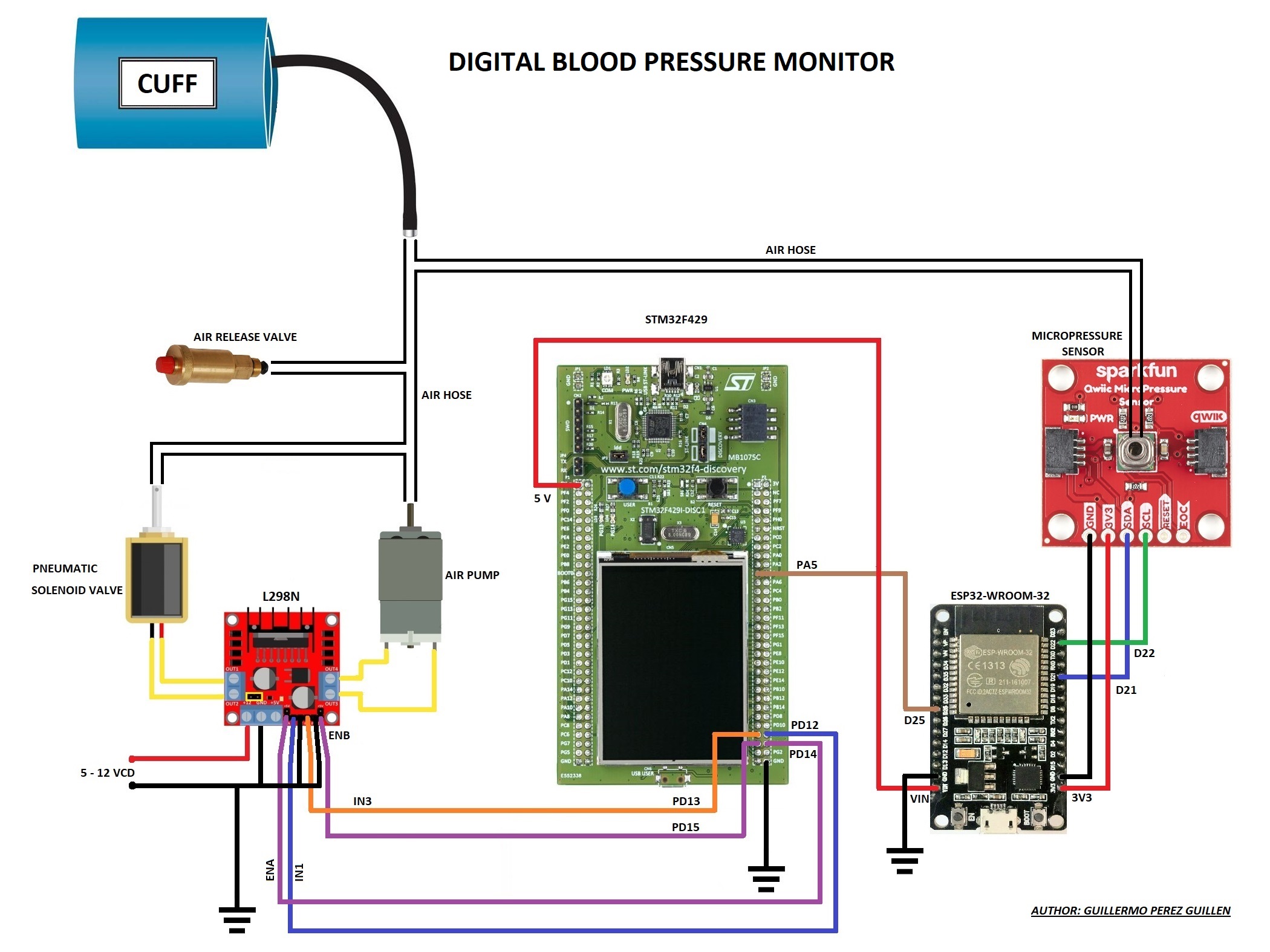
Our schematic diagram is shown below:
- The analog port PA5 of the STM32F429I board is connected to the DAC_1 port of the ESP32-WROOM-32 board, so we will monitoring each mmHg of the pressure sensor in real time.
- When we press the user button (blue) that corresponds to port PA0, then the air pump and the pneumatic solenoid valve are turned ON.
- In this solenoid the valve closes and doesn't allow any air leakage, so the air pump begins to inflate the cuff, and the pressure sensor tells us how the pressure increases inside the cuff.
- Each increase in pressure within the cuff is printed on the LCD screen of the STM32F429I board.
- You have to note that before printing the total pressure I do a subtraction of eight units, this is because I found a small error of + 8 mmHg approx in all my readings. I did this verification with an aneroid gauge.
- When the pressure inside the cuff reaches 170 mmHg, then the air pump is stop (OFF), and the solenoid valve continues closed.
if STM32.User_Button.Has_Been_Pressed then -- Btn pressed then go to 170 mmHg
         Start_Conversion (Converter);
         Poll_For_Status (Converter, Regular_Channel_Conversion_Complete, Successful);
         Solenoid_valve.Set;   -- solenoid valve is ON
         Motor.Set;   -- air pump is ON
         Enable_a.Set;
         Enable_b.Set;
         Raw := UInt32 (Conversion_Value (Converter));
         Volts := UInt32  ((Float (Raw) / 4096.0) * 3000.0);   -- 4096 ADC = 3000 mV
         Pressure := UInt32 ((Float (Volts) / 3000.0) * 255.0);   -- 3000 mV = 255 mmHg
         Pressure_total := UInt32 (float (Pressure) - 8.0);   -- 3000 mV = 255 mmHg
         Print (0, 0, Pressure_total, " mmHg"); -- print blood pressure

         while Pressure_total <= 170 loop
            Start_Conversion (Converter);
            Poll_For_Status (Converter, Regular_Channel_Conversion_Complete, Successful);
            Raw := UInt32 (Conversion_Value (Converter));
            Volts := UInt32  ((Float (Raw) / 4096.0) * 3000.0);   -- 4096 ADC = 3000 mV
            Pressure := UInt32 ((Float (Volts) / 3000.0) * 255.0);   -- 3000 mV = 255 mmHg
            Pressure_total := UInt32 (float (Pressure) - 8.0);   -- 3000 mV = 255 mmHg
            Print (0, 0, Pressure_total, " mmHg"); -- print blood pressure
            delay until Clock + Milliseconds (75);
         end loop;

         Solenoid_valve.Set;   -- solenoid valve is ON
         Motor.Clear;   -- air pump is OFF
         Enable_a.Set;
Enable_b.Clear;- Continuing with the narration from the previous section. The cuff starts to deflate from 170 mmHg.
- Remember that the solenoid valve is closed, so now the air leak is in the air release valve. Here, the recommendation is that the deflation process of the cuff is between 17 and 21 seconds. So we must calibrate this air release valve with a flat screwdriver, so if we turn it clockwise then the valve closes, and counterclockwise the valve opens.
- The next step is to measure blood pressure values between 70 mmHg and 170 mmHg and save them in the "PressureArray" matrix every 200 ms approximately.
- I have programmed a maximum value of 210 mmHg in the while function in case, during the inflation of the cuff, it exceeds the limit of 170 mmHg, for example 180 mmHg.
- The values stored in the "PressureArray" matrix and per test are between 120 and 130.
while Pressure_total > 70 and Pressure_total <= 210 loop
            Start_Conversion (Converter);
            Poll_For_Status (Converter, Regular_Channel_Conversion_Complete, Successful);
            Raw := UInt32 (Conversion_Value (Converter));
            Volts := UInt32  ((Float (Raw) / 4096.0) * 3000.0);   -- 4096 ADC = 3000 mV
            Pressure := UInt32 ((Float (Volts) / 3000.0) * 255.0);   -- 3000 mV = 255 mmHg
            Pressure_total := UInt32 (float (Pressure) - 8.0);   -- 3000 mV = 255 mmHg
            Print (0, 0, Pressure_total, " mmHg"); -- print blood pressure

            PressureArray(X_Pos) := Integer (Pressure_total);
            X_Pos := X_Pos + 1;
            delay until Clock + Milliseconds (190);
end loop;- We already have all the data stored in the "PressureArray" matrix. Now our goal is to find these points where the Korotkoff sounds occur.
- I did a test, send and graph to excel all the points of the curve of my blood pressure to see the points where the Korotkoff sounds occur, and this is what I saw.
Here you can get a tutorial to send the data to Excel: https://github.com/gsampallo/serialToExcel
And you can download my excel file at this link: Korotkoff_sounds_excel
- In the graph above I found ten Korotkoff sounds. I did an analysis and in all Korotkoff points I found the following two constants: 1) point b is greater than point a, and 2) point c is greater than point a.
- Through a for loop I'm going to go through 130 records of the "PressureArray" matrix. Next, I assign the first record to the variable "var_a", the second record to the variable "var_b" and the third record to the variable "var_c".
- If the variables "var_b"> "var_a" and "var_c"> "var_a", then I print the variable "var_b" as Korotkoff sound.
- Any other combination I only delay 1 ms. and I don't print anything.
- According to the theory read at the beginning of this tutorial (sections 2 and 3), systolic pressure is the first Korotkoff sound, and diastolic pressure is the last Korotkoff sound.
for I in 1 .. 130 loop
            var_a := UInt32(PressureArray(I));
            var_b := UInt32(PressureArray(I+1));
            var_c := UInt32(PressureArray(I+2));

            if var_b > var_a and var_c > var_a then

               Print (0, Integer (inc), var_b, " mmHg-korot");
               inc := inc + 25;
               delay until Clock + Milliseconds (1);

            else

               delay until Clock + Milliseconds (1);

            end if;

end loop;The hardware is assembled in a box for the best handling of the device, in the figure below we can see the box made with a 3D printer, and whose STL file you can get in the download section.
Next, we join the solenoid valve with the connector through which the cuff can be connected.
Now we glue these pieces with silicone over the box's groove shown in the figure below.
I have used a smaller air pump to best fit in the box. So, we join this air pump to the cuff connector with an air hose as shown in the figure below. Also we join the air release valve to the cuff connector with an air hose.
We connect the micro pressure sensor with the air pump with an air hose. Then we fix the pressure microsensor as shown in the figure below.
The next step is to fix the ESP32-WROOM-32 board as shown in the figure below.
Finally, place the STM32F429I board and the L298N driver as shown in the figure below. All electrical connections are followed as in the schematic diagram.
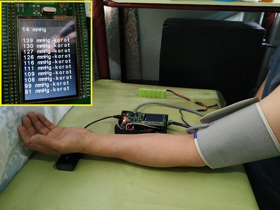
In the video below I show you my first tests with this health device. In the first part, we see a test where I get six Korotkoff sounds. In the second part I did a close up, so you can see the data on the LCD screen.
To increase the amount of Korotkoff sounds detected I did two things:
- The air release valve must be recalibrated, so I gave it more time so that the device had time to detect more Korotkoff sounds (Reference: second point of section 7); and
- Foam rubber must be added to the air pump to reduce device vibrations, because these vibrations induce noise in other devices.
I've getting ten Korotkoff sounds in this test, and we can see them in the figure below:
Korotkoff sounds:
- 139 mmHg
- 130 mmHg
- 127 mmHg
- 126 mmHg
- 116 mmHg
- 111 mmHg
- 109 mmHg
- 106 mmHg
- 99 mmHg
- 81 mmHg
Finally, I had check my blood pressure and compare it to the second test.
Notes:
- At that time I was suffering from a slight flu, so the values can be considered justified.
- The OMRON digital pressure gauge detects Korotkoff sounds while the cuff is inflated. My design detects Korotkoff sounds while the cuff deflates.
DATA COMPARISONS:
- My device: according to the theory seen on sections 2 and 3, my systolic pressure is 139 mmHg, and my diastolic pressure is 99 mmHg (or 81 mmHg).
- The OMRON device: it tells me that my systolic pressure is 137 mmHg, and my diastolic pressure is 95 mmHg.
To develop this project I learned that it's necessary to verify and analyze each step to follow, eg:
- Pressure measurements of this device were compared with an aneroid manometer.
- I had to calibrate the air release valve several times.
- This model can be useful for a doctor or nurse who suffers from a bad hearing, because it would be imposible to detect the Korotkoff sounds.
- In the final tests I feel satisfied with the values measured by my device when I compare it with the OMRON device.
This project is complex, so I suggest the following challenges to improve it:
- Make the pressure sensor libraries to connect it directly with the STM32F429I board;
- Another option to the previous point would be to communicate the ESP32-WROOM-32 and STM32F429I boards through the serial port;
- Calculate the heart rate from the Korotkoff sounds; and display the hart rate with the systolic and diastolic pressure on the screen;
- Develop the prototype with the oscillometric method. To achieve this, it's necessary to test with analog and/or digital bandpass filters. At the end you have to make an algorithm to combine the oscillometric method and the Korotkoff sounds.
This is how a digital blood pressure monitor is manufactured.


_9nsOFQ7ama.png?auto=compress%2Cformat&w=48&h=48&fit=fill&bg=ffffff)


Comments
Please log in or sign up to comment.