


Hardware components | ||||||
 |
| × | 1 | |||
| × | 1 | ||||
 |
| × | 1 | |||
 |
| × | 1 | |||
| × | 1 | ||||
| × | 1 | ||||
 |
| × | 2 | |||
| × | 2 | ||||
 |
| × | 4 | |||
Hand tools and fabrication machines | ||||||
 |
| |||||
 |
| |||||
From the first instance I gazed upon the awesomeness that is a lightsaber, I knew Star Wars would be my comfort universe. The shear amount of content that has been produced in the Star Wars universe has fueled my love for it to this day. My favorite movie is Rogue One and my favorite characters are Ahsoka Tano and Obi-won Kenobi. In addition to being objectively awesome, they both demonstrate a sense of self that I somewhat admire.
Anyways, the kid engineer in me really came out as I was working on this project. There was never a day that I didn't enjoy contemplating how to thread my components in code or how to make the lightsaber flicker in a way that at least sort of resembled the movies.
In all, my lightsaber has the ability to "light up" and "light down" as well as a few cool animations in between. The color choice is customizable to fir however the force presents itself in the beholder.
This page described the hardware and software integration that was implemented to create a realistic...well... very homemade looking and acting lightsaber.
This project drew great inspiration from Erik Welsh and the work of Mustafa Latif and Liam McConnico-Blanchet.
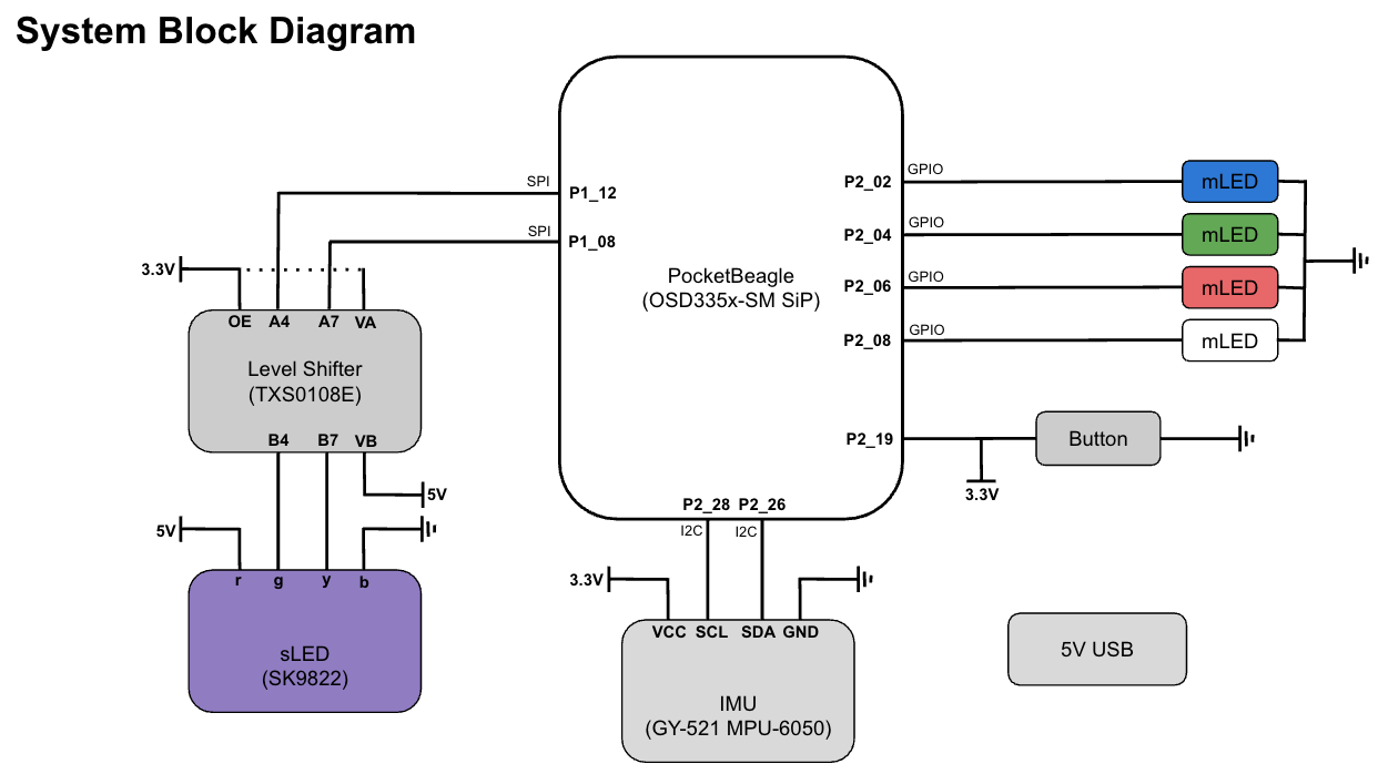
Build Instructions:There are 7 main components or objects of my lightsaber design. They include the buttons, mini LEDs (mLEDs), a strip LED (sLED), gyroscope/accelerometer (IMU), Level Shifter (LS), and Power Source. They are all routed to a PocketBeagle (PB). I will lay out how everything is hooked up below:
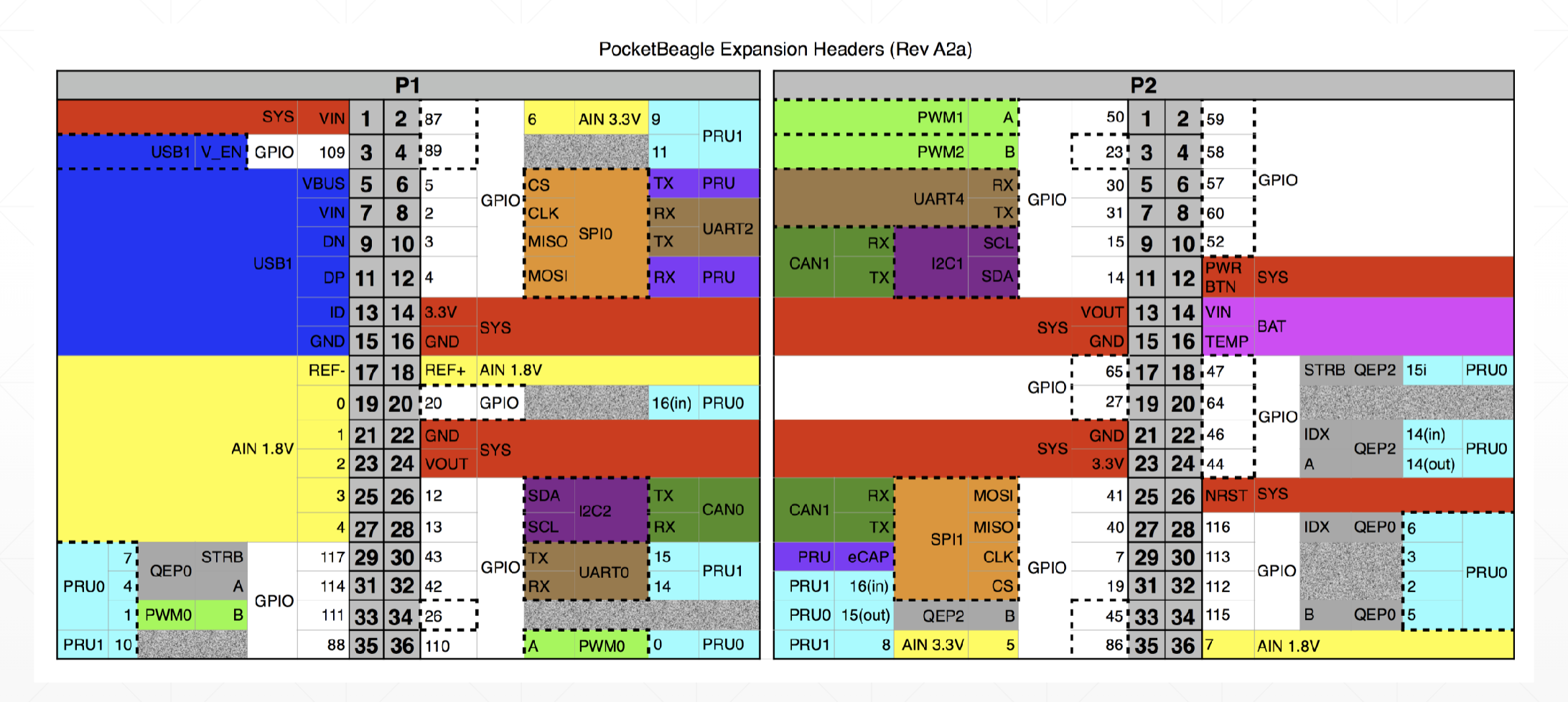
PocketBeagle
For this project, we used PocketBeagle as the computer. Erik Welsh provided all components used for the project, and our PocketBeagles had pre-soldered pins and were attached to a breadboard. All components will be connected to the PocketBeagle for power and software implementation. Pin P2_23 of the PB is connected to the right side (+) rail to serve as the 3.3V power rail. Pin P2_21 is connected to the right side (-) rail to serve as a GND rail.
------------------------------------------------------------------------------------------------------------------
Power Source
Since the sLED needed a 5V Power Source, and the PB cannot output above a 3.3V, I included a 5V Power Source, pictured below, that hooked up directly to the sLED. In the future, I hope to be able to hook the 5V source into the PB so that everything can move off-line. The Power Source needs an adapter to interface with the wires needed to connect to the Breadboard and PB. The adapter is pictured below. The white wire is the 5V connection and is connected the (+) rail on the left side of the board. The black wire is GND and is connected to the (-) rail on the left side of the board.
------------------------------------------------------------------------------------------------------------------
Buttons
Currently, two buttons are implemented in my system, however, only one contributes to the overall function of my lightsaber. So, I will only discuss that button. The button is connected to pin P2_19 configured as a GPIO. It is connected with a 1 kOhm resister to 3.3V power and then to ground. At default, the button has a "1" and when pressed, has a value of "0." Below is a sketch of the routing and a picture of it on the breadboard.
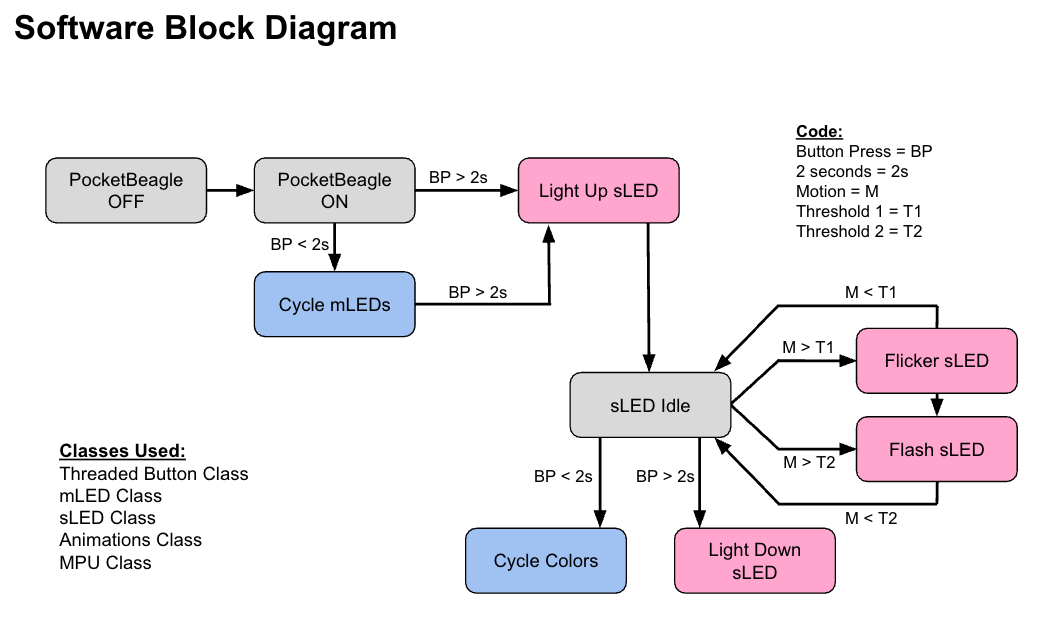
The button is used in two ways. Pressing it for less than 2 seconds changes the color (based on mLEDs which will be explained in the next section). Pressing it for longer than 2 seconds, causes the sLED to power up (animated to reflect the pattern of a real lightsaber).
------------------------------------------------------------------------------------------------------------------
Mini LEDs
There are 4 mLEDs hooked up to the PB. There is a blue, green, red, and white mLED. They are all hooked up in the Active High Configuration as shown in the sketch below. Their pin connections (to the PB) are as follows:
blue mLED = P2_02green mLED = P2_04red mLED = P2_06white mLED = P2_08
These mLEDs are used to indicate which color the blade (sLED) will be when lit up. You can change colors with the sLED lit up or without it lit up. The sLED is programmed to match the color of the mLED that is on. You can use the button to change colors.
------------------------------------------------------------------------------------------------------------------
Strip LED
The sLED strip needs to be powered using 5V, however, the PB works with 3.3V. Thus, a level shifter (LS) is needed to operate the system. The LS will be described in the next section. The sLED has 4 wires that are used to hook them up. Their values and colors are as follows:
red wire = Powergreen wire = Data Signal Inputyellow wire = Clock Signal Inputblack wire = GND
The red wire will be connected to the 5V rail which is powered by the 5V Power Source and the black wire will be connected to the GND rail. The green wire is connected to pin B4 of the LS and the yellow wire is connected to pin B7 of the LS.
The sLED has several animations worked into the software of this system. That will be described later. Thus, SPI connections are needed.
------------------------------------------------------------------------------------------------------------------
Level Shifter
The Level Shifter requires the set up as shown below. It is used to relate the 3.3V and 5V components. Side B is connected to the 5V Power Source and Side A is connected to the 3.3V Power Source. The LS can be thought of as a meeting point for the sLED and PB pin connections.
Note that OE and VA are connected. Note that the GND rails (left and right (-) rail) need to be connected. Note that B4 connects to A4 and B7 connects to A7. Note that VB connects to the 5V power rail and VA connects to the 3.3V power rail. All connections are shown in the pic below.
------------------------------------------------------------------------------------------------------------------
IMU
The IMU is a motion sensor that will detect movement and rotation of the lightsaber. Acceleration and impact can be calculated using the data taken from this device to drive light animations of the lightsaber. Soldering was required to implement this component on the breadboard.
This component is connected as shown below. Its main connections are to the 3.3V Power and GND rails and then to the I2C2 pins (P1_26, P1_28) of the PB. It requires I2C to communicate with the PB.
The IMU also has an INT pin which is depicted above, however, it doesn't need to be hooked up in order to function. The INT pin offers a way to have a master switch that can interrupt any function currently being used to initiate a another function or action. I used this tool to code for a flash animation.
------------------------------------------------------------------------------------------------------------------
Final Product:Shown below is the full integrated hardware design including all components described above.
------------------------------------------------------------------------------------------------------------------
Operation:To use this lightsaber, pressing the button for less than 2 seconds will cycle through the mLEDs. Once you have chosen to be a part of the light side or dark side, you can hold the button for longer than 2 seconds to ignite the blade. A light up animation will follow which lights up the sLED blade from handle to tip. If you would like to change colors while the sLED is ignited, you can press the button for less than 2 seconds to cycle through the 4 possible colors (the mLEDs and sLED will change in tandem). Then, if you would like to holster you lightsaber, you can press the button for longer than 2 seconds to initiate the light down animation which turns the sLED off from tip to handle.
While the sLED is one, the IMU will constantly take data readings and transmit them to the PB. If the movement of the blade is above a threshold, the sLED will flicker just as it would in real life (looks like a flickering candle). This is controlled by a flicker animation. Then, if you find yourself in a dual and clash light sabers with an enemy, a second threshold, controlled by the INT pin as described in the IMU section will cause the sLED to flash, controlled by flash animation.
------------------------------------------------------------------------------------------------------------------
Next StepsCurrently, the lightsaber is fully functional with all of the hardware described on this page (except for the extra button). There is a little bit of variation with the flicker and flash animations that can be attributed to the software side of the project which can be found in the GitHub Repository linked below.
In the future, a speaker can absolutely be included to produce the typical gentle hum which is typically depicted in Star Wars media. Further, this could also be used to produce variations in the humming to match the animations of the sLED. For example, a more aggressive hum when the flickering animation is triggered. Another strip of LEDs could also be added.
Finally, the current design has not been moved off of computer connection because of some issues with power source connections and boot and run difficulties. Ideally, this would be resolved so that the lightsaber can function on its own. I would also love to see a 3D printed hilt and a more realistic blade material than what I used (a broomstick stolen from my roommates...they aren't too happy with me about that). This would enhance the overall aura of the lightsaber.
-----------------------------------------------------------------------------------------------------------------


_3u05Tpwasz.png?auto=compress%2Cformat&w=40&h=40&fit=fillmax&bg=fff&dpr=2)


Comments
Please log in or sign up to comment.