


Software apps and online services | ||||||
 |
| |||||
Hand tools and fabrication machines | ||||||
 |
| |||||
 |
| |||||
Thanks again @PCBWay for sponsoring my project. PCBWay You can have your PCB boards produced for 5$. And it provides all kinds of printing and assembly services.
PCBWay: https://www.pcbway.com/
PCBWay+ my profile: https://www.pcbway.com/project/member/?bmbno=188E1A91-204D-49
Youtube:
Hello, today I am here with an interesting project in this project:
Arduino Uno
L293B motor driver 2 units
A4988 stepper motor driver
and mini breadborad
we used it, now you want, let's examine the connection diagrams.
L293B connection diagram:
WhatisL293B:(Source: Datasheet. CLICK to reach.)
L293B is a motor driver IC. This IC is a tool that allows microcontrollers (e.g. Arduino or Raspberry Pi) to control motors. The L293B can be used for both DC motors and stepper motors.
The L293B is designed in a structure known as two H bridges. Each H bridge contains two transistors and two diodes. This structure is used to change the direction of motors. There are four motor outputs on the IC and these outputs control its speed using PWM (Pulse Width Modulation) signals.
The L293B IC can be used with power supplies up to 36V and can provide an output current of up to 1.2A. Thanks to these features, the L293B is a viable option for many applications.
The integration is very simple to use. First, the motors need to be connected to the power supply. Then, a suitable microcontroller (for example Arduino) is connected to the L293B IC. A code is written to control the direction and speed of the motors and this code is sent to the L293B IC by the microcontroller.
The advantages of the L293B IC include high current and voltage tolerance, ease of use and low cost. However, there are also some disadvantages. For example, due to the high current, the integrated may heat up and require cooling. Also, the L293B IC may make noise due to the high current.
L293B disadvantages:
Some disadvantages of the L293B IC are:
- Heating: L293B IC may become hot due to high current and voltage application. Therefore, the IC may need to be cooled. Without good cooling, the life of the L293B can be shortened.
- Noise: L293B can make noise due to high current and voltage. Therefore, this noise can be a problem in some applications.
- Limited current capability: L293B's maximum output current is 1A. Therefore, it is not suitable for applications with high current needs such as large stepper motors. Suitable driver ICs should be preferred for large stepper motors.
- High power consumption: L293B IC is not suitable for battery powered applications due to its high power consumption. For battery-powered applications, driver ICs with lower power consumption should be preferred.
- Low efficiency: L293B IC can cause high voltage drop. This causes the integrated to have low efficiency.
- It can be expensive: In some cases, the L293B IC may be more expensive than other stepper motor driver ICs. Therefore, other options are available for those looking for a cost-effective solution.
These disadvantages are quite minor compared to the advantages of the L293B IC. However, with proper use and configuration, these disadvantages can be mitigated.
LM293B arduino connection:
L293B IC is used to control devices that require high current and voltage such as stepper motors and DC motors. The connection of L293B with Arduino is as follows:
- Power connections: L293B's power connections are connected to Arduino via 5V and GND pins. The L293B receives power from the motors via the power connections.
- Control connections: L293B's control connections are connected via Arduino digital pins. The L293B controls the direction and speed of the motors via the control connections.
- Motor connections: L293B's motor connections contain 4 pins separately for stepper motors and DC motors. These pins are used for connecting motors.
The picture below shows the connection of the L293B IC with the Arduino:
Source: Google.com.
In this circuit diagram, the power connections of the L293B IC are connected to the Arduino via the 5V and GND pins. L293B's control connections are connected via Arduino's digital pins 6, 7, 8, 9. and 10. The motor connections are connected via pins 1, 2, 3, of the L293B.
// Arduino connection with L293B IC and DC Motor.

int motorPin1 = 2;
int motorPin2 = 3;
int enablePin = 4;

void setup() {
  pinMode(motorPin1, OUTPUT);
  pinMode(motorPin2, OUTPUT);
  pinMode(enablePin, OUTPUT);
}

void loop() {
  digitalWrite(motorPin1, HIGH);
  digitalWrite(motorPin2, LOW);
  analogWrite(enablePin, 200);
  delay(2000);
  digitalWrite(motorPin1, LOW);
  digitalWrite(motorPin2, HIGH);
  analogWrite(enablePin, 150);
  delay(2000);
}
WhatisL293B:(Source: Datasheet. CLICK to reach.)
A4988 is a stepper motor driver IC. It is used to control the speed, direction and step angle of stepper motors. The A4988 IC applies high current and voltage to the stepper motors, allowing motors to be controlled more accurately and precisely.
A4988 can be applied to bipolar stepper motors and can make more precise step control thanks to its micro-stepping feature. Thanks to this feature, it is possible to reduce the vibration of the stepper motors and ensure their quieter operation.
A4988 offers 8 microstep resolution options. This feature allows the stepper motor to move in finer steps. A4988 supports up to 1/16 step microstep resolution.
The operating voltage of the IC ranges from 8V to 35V and the maximum output current is 2A. Thanks to these features, the A4988 is a viable option for many applications.
A4988 IC is compatible with TTL and CMOS logic levels and can be used easily. It is compatible with many microcontrollers (e.g. Arduino or Raspberry Pi) and is simple to use.
The integration is very simple to use. First, it needs to be connected to the stepper motor and power supply. Then, the A4988 IC is connected to a suitable microcontroller. A code is written to control the direction, speed and step angle of the stepper motor and this code is sent to the A4988 IC by the microcontroller.
The A4988 IC is an ideal tool for many applications with its many advantages. The integrated is easy to use and the stepper motors can be controlled more precisely thanks to the micro-step feature. However, due to the high current, the integrated may heat up and require cooling. Also, the A4988 IC may make noise due to the high current.
The A4988 IC is a suitable option for many stepper motor projects.
A4988 disadvantages:
High heating: The A4988 may become hot due to high current and voltage application. Therefore, the IC may need to be cooled. Without good cooling, the life of the A4988 can be shortened.
- Noise: A4988 may make noise due to high current and voltage. Therefore, this noise can be a problem in some applications. However, this noise can be reduced thanks to the micro-step feature.
- Limited output current: The maximum output current of A4988 is 2A. Therefore, it is not suitable for larger stepper motors. Suitable driver ICs should be preferred for large stepper motors.
- Requires precise voltage control: The A4988 IC requires precise voltage control. If the voltage values are set incorrectly, the stepper motor may not operate correctly. For this reason, it is necessary to configure the IC correctly and make the voltage settings carefully.
- It may not be cost-effective: In some cases, the A4988 IC may be more expensive than other stepper motor driver ICs. Therefore, other options are available for those looking for a cost-effective solution.
These disadvantages are quite small compared to the advantages of the A4988 IC. However, with proper use and configuration, these disadvantages can be mitigated.
A4988 arduino connection:
Requirements:
Arduino Uno
A4988 Stepper Motor Driver Integrated
Bipolar Stepper Motor
jumper cables
Connection diagram:
Arduino A4988
5V -> VDD
GND -> GND
D8 (PB0) -> STEP
D9 (PB1) -> DIR
D10 -> MS1
D11 -> MS2
D12 -> MS3
ot: The MS1, MS2 and MS3 pins are used to specify the microstep resolution and are optional. If these pins are left idle, the A4988 works in full step mode.
Connection steps:
Connect the A4988 driver IC to the 5V and GND pins of the Arduino.
The windings of the bipolar stepper motor must be connected to the A and BOUT pins of A4988.
Connect Arduino's D8 (PB0) pin to A4988's STEP pin.
Connect Arduino's D9 (PB1) pin to A4988's DIR pin.
Optionally, you can connect Arduino's D10, D11 and D12 pins to A4988's MS1, MS2 and MS3 pins to determine the microstep resolution.
After the connection process is complete, you can control the speed and direction of the stepper motor by writing Arduino code.
// Arduino connection with A4988.
#define dirPin 9
#define stepPin 8
void setup() {
pinMode(dirPin, OUTPUT);
pinMode(stepPin, OUTPUT);
digitalWrite(dirPin, 0);
}
void loop() {
int delayTime = 1000;
for(int i=0; i<200; i++) {
digitalWrite(stepPin, HIGH);
delayMicroseconds(delayTime);
digitalWrite(stepPin, LOW);
delayMicroseconds(delayTime);
}
delay(1000);
digitalWrite(dirPin, 1);
for(int i=0; i<200; i++) {
digitalWrite(stepPin, HIGH);
delayMicroseconds(delayTime);
digitalWrite(stepPin, LOW);
delayMicroseconds(delayTime);
}
delay(1000);
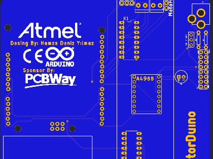
}What will it do in card design?
This board is already designed for motor control, as you will see in the controller, I used arduino uno. I used L293B on this board. For those who ask why you didn't use the L293D instead, here is my answer:
L293B and L293D are two different driver ICs. The L293B is the previous version of the L293D and has similar features, but with some differences.
The most obvious difference is that the L293D provides a higher output current compared to the L293B. The L293D can provide 1.2 A output current, while the L293B can only provide 1 A output current. Therefore, the L293D is more suitable for higher power motors and loads than the L293B.
In addition, the L293D has more protection features than the L293B. The L293D automatically cuts the circuit in cases such as overheating, overcurrent and overvoltage. This means the L293D is the safer and more robust choice.
L293D and L293B are similar driver ICs in the same high voltage class and basically perform the same functions. However, for high power applications, the L293D is a better choice than the L293B.
If you say why not 1 but 2, to drive more motors.
Anyone can say "You can do this on a breadboard" now but my goal was to collect them all in one place and to make it look neat and beautiful.
There may be those who say that the card is unnecessary, that it is empty, but in my opinion, success is up to the person who does it and does not, that is, it is entirely up to the person's own opinion. I loved it like that, I did it like this
The reason why these projects are open-source is that I am publishing them so that people can buy these projects and make changes on them so that better designs and better projects emerge.
More to come, stay tuned.
Thanks for reading this far.
Many thanks to PCBWay for sponsoring me


Comments
Please log in or sign up to comment.