I have an electric IKEA Bekant sit/stand desk. It's designed so that you need to hold down the up and down buttons for the desk to move. The desk takes about twelve seconds to move from a comfortable sitting position to a standing position, and vice versa, for me. I certainly don't have time to wait for minutes... MINUTES I TELL YOU... per day to push a button.
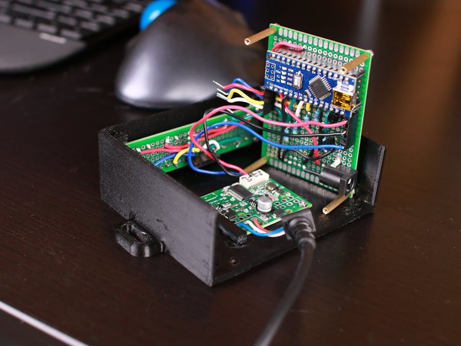
I made a simple automater using an Arduino Nano, some N-channel mosfets, several momentary switches, and the original desk control PCB cannibalized from a spare control panel I had shipped to me.
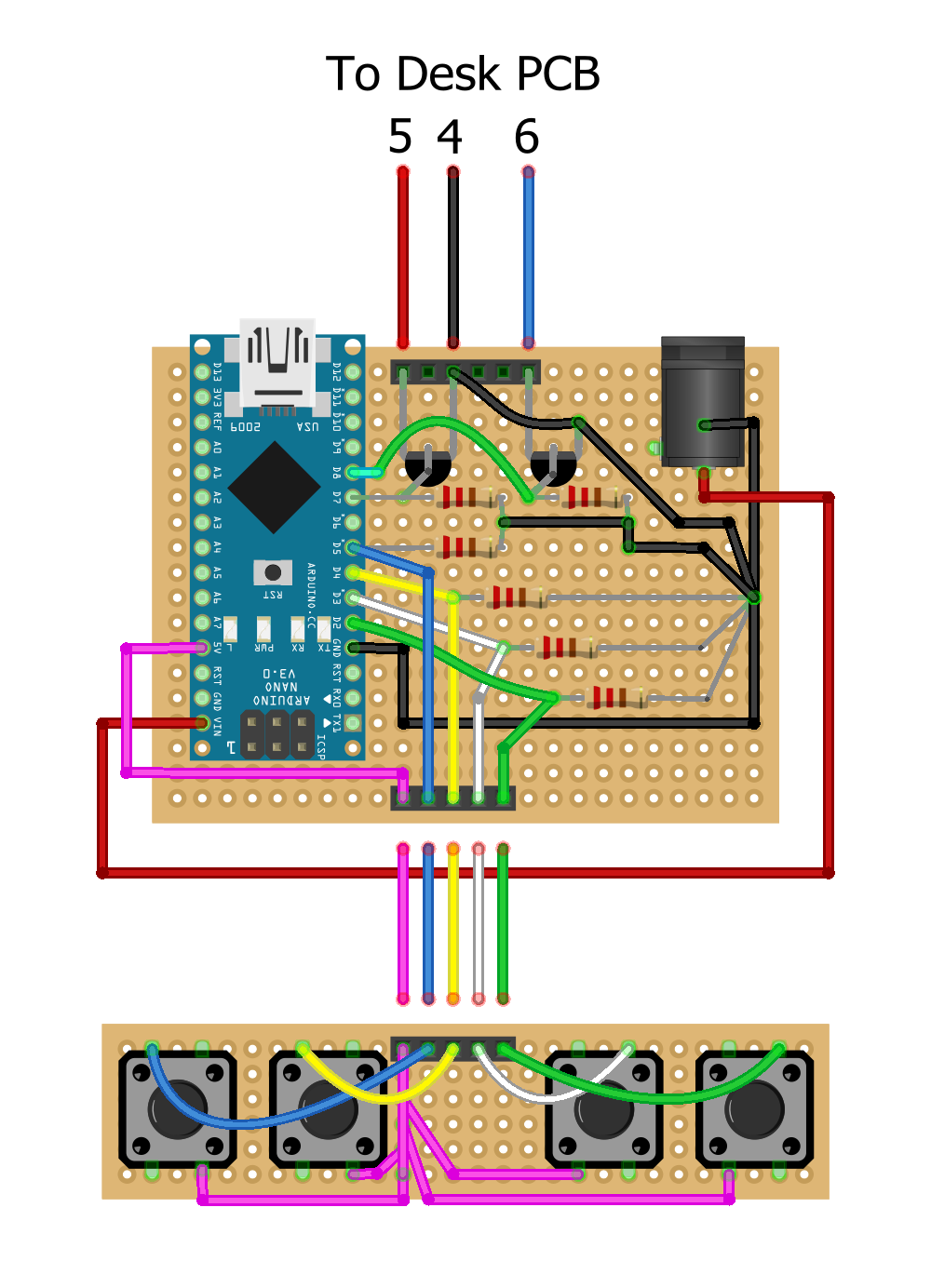
While I could have used an actual schematic, I'm hoping the included Fritzing diagram will help ease the circuit layout process for anyone re-creating this project.
***All screws, washers, nuts, and standoffs are M2***
***All wire is 22awg solid-core***
--- Parts I used ---
1x Power jacks
2x MOSFETs
4x Buttons
4x Button caps
4x Standoffs
6x 220 Ohm resistors
1x Power source with a 5.5mm x 2.1mm jack (Any 7-12V wall wart should do since Nanos can tolerate that range. You don't need much current as the circuit is only running logic. I used a 9V, 1A supply... way overkill on the amps, but it's what I had on hand.)
------------------
Step 1) Print the enclosure parts, cleaning up the holes on the bottom surface of the body so that a washer and screw head sit below flush from the surface (the flat side will be placed flat against the underside of the desk).
Step 2) Remove the control panel from your desk.
Step 3) Open up the control panel case using a dremel, pliers, cutters, and/or a screwdriver as needed and remove the flexible button PCB. BE CAREFUL NOT TO DAMAGE THE PCB! It is only slightly below the control panel case you'll be cutting. IKEA sent me a spare, but shipping takes a while.
Step 4) Solder the two boards shown below (What I call the "main PCB" in the video is on top, and the "button PCB" is on the bottom; I realize they aren't technically PCBs, I just want to remain consistent with the video's phrasing). Be sure to add headers underneath the pins of the Nano; don't solder the Nano directly to the board (it makes replacement easier later, if necessary).
The main PCB has 24 columns, 18 rows. The button PCB has 28 columns, 6 rows. All resistors are 220 Ohm. You will have to drill out one of the holes to fit the negative lead of the power jack. After drilling, bend it over and solder it to a nearby hole for structural support.
Step 5) Upload the code to the Nano and install it onto the main PCB.
Step 6) Super glue the desk PCB holder to the case body.
Step 7) Place nuts into the four slots of the case body (this may be difficult as sometimes they fall out, take your time). It helps to slip one nut in place, then hold it there loosely with a screw. Do so with all four nuts BEFORE attaching the button PCB. Then, tilt the case body to one side, remove the screws on the lower side, keeping the nuts in their slots. Loosely attach the button PCB to that side of the case body using 10mm or greater screws, just enough to hold the PCB and nuts. Then repeat for the other side with 6mm screws (the final screw size). Finally, replace the 10mm screws on the first side with 6mm screws and tighten them all.
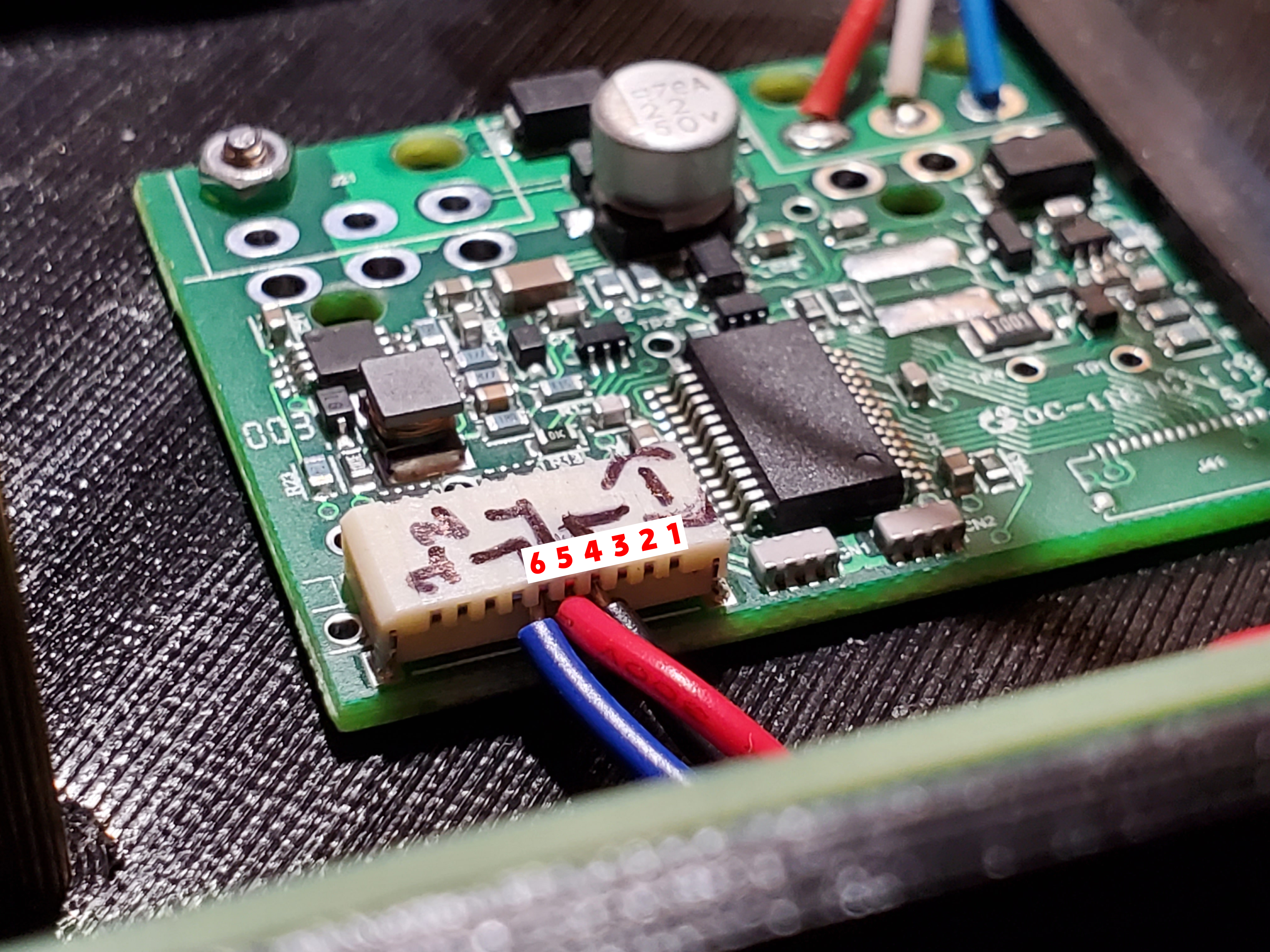
Step 8) Attach three jumper wires into the header of the desk PCB, according to the wiring diagram and the photo below. The insulated portions of mine were about 75mm long (leave extra to plug into the headers). You'll want some length for maneuvering the main PCB into place later.
Step 9) Slip the desk PC under the desk PCB holder, then secure with a 6mm screw and washer through the bottom of the case body, and a nut on top.
Step 10) Install 20mm standoffs using washers and 8mm screws. These will hold the four corners of the main PCB.
Step 11) Attach five jumper wires to the main PCB header facing the button PCB and bend them into a U. The insulated portions of mine were about 22mm long (again, leave extra to plug into the headers).
Step 12) Insert the jumpers from the desk PCB into the remaining main PCB header using the wiring diagram, then attach the main PCB upside down on the standoffs using nuts.
Step 13) Using pliers, carefully insert the five jumpers from the main PCB into the header of the button PCB, referencing the wiring diagram as needed.
Step 14) Place nuts into the four slots of the case cover. Make sure to press them to the bottom of the slots, otherwise the screws won't thread into them properly.
Step 15) Place the case cover onto the case body, making sure to slide the grommet of the desk PCB properly into the cutout. Slide the case cover backward over the Nano USB port and the power port, then secure with washers and 16mm screws.
Step 16) Mount the device underneath your desk using wood screws. I used 16mm. You can use other lengths, just MEASURE BEFOREHAND SO YOU DON'T BREAK THROUGH THE TOP SURFACE... keeping in mind 3D printed plastic will compress as you tighten the screws. I recommend hand-tightening these so you don't split the screw tabs.
Step 17) Plug the desk PCB cable into the desk and attach the power source to the main PCB power port.
Step 18) Test the buttons again to make sure each one moves the desk as intended. There should be one button that automatically moves the desk up for an extended period once pressed and released (STAND), one that automatically moves the desk down for an extended period once pressed and released (SIT), one that moves it upward as long as you hold it (UP), and one that moves it down as long as you hold it (DOWN)
My chosen configuration from left to right is STAND, SIT, UP, DOWN.
Step 19) Adjust the code and re-upload as needed to get the button configuration and automated movement length you want. Now go and enjoy your automated desk! Go on, move it up and down a few times... you know you want to.


Comments
Please log in or sign up to comment.