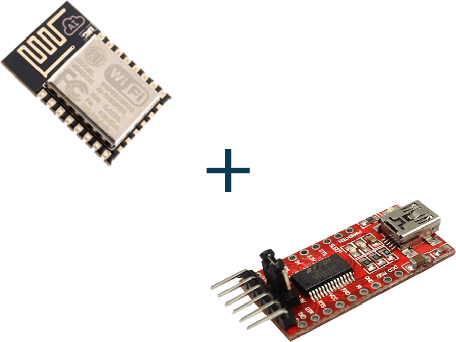
Learn how to program ESP8266 ESP-12E with Arduino using FTDI USB to TTL cable. You just need to install the ESP8266 board and make the circuit as per the below-given instructions. For basics and features of ESP8266 ESP-12E click here.
Connect pins as per the below given instructions.
- FTDI VCC to ESP8266 ESP-12E VCC and GPIO_2
- RTS/CTS to CH_PD
- DTR to GPIO_0
- GND to GND and GPIO_15
- TX to RX and RX to TX.
Make the circuit as per the above-given instructions. Connect the FTDI cable to the USB port. Select the proper board and programmer. Upload the sample code to ESP8266 ESP-12E.
Bootloader Modes of ESP-12EBootloader ModesThe bootloader can go into a number of modes depending on the state of GPIOs 0, 2 and 15. The two useful modes are the UART download mode (for flashing new firmware) and the flash startup mode (which boots from flash).
- Flash Startup (Normal) GPIO0: 1 GPIO2: 1 GPIO15: 0
- UART Download Mode (Programming) GPIO0: 0 GPIO2: 1 GPIO15: 0
- SD-Card Boot GPIO0: 0 GPIO2: 0 GPIO15: 1
For basic information and uploading code using FTDI USB to TTL Cable, Click Here. For installing ESP8266 board to Arduino IDE, Click here.
Source: https://iot-guider.com/ftdi-usb-to-ttl/program-esp8266-esp-12e-with-arduino-using-ftdi/


_3u05Tpwasz.png?auto=compress%2Cformat&w=40&h=40&fit=fillmax&bg=fff&dpr=2)
Comments