


Hardware components | ||||||
_ztBMuBhMHo.jpg?auto=compress%2Cformat&w=48&h=48&fit=fill&bg=ffffff) |
| × | 1 | |||
| × | 1 | ||||
 |
| × | 4 | |||
| × | 6 | ||||
| × | 6 | ||||
 |
| × | 4 | |||
| × | 8 | ||||
| × | 3 | ||||
| × | 1 | ||||
| × | 2 | ||||
 |
| × | 1 | |||
 |
| × | 1 | |||
| × | 2 | ||||
| × | 50 | ||||
| × | 1 | ||||
 |
| × | 30 | |||
 |
| × | 20 | |||
| × | 1 | ||||
Software apps and online services | ||||||
| ||||||
| ||||||
| ||||||
| ||||||
Hand tools and fabrication machines | ||||||
| ||||||
 |
| |||||
| ||||||
 |
| |||||
 |
| |||||
Summary
To develop a CNC need you to learn about code, IT, electricity, electronics, and mechanics skills. One method to build a CNC is described below, step by step.
After a paced process, and a lot of interruptions, you can watch operating the machine I built , in the following video:
I took my first challenge with a mini CNC DIY, this machine partially worked; I didn't get the stage of install the Z axe. The idea was to built it as cheap as possible, in this video you can watch the results:
"I had a dream"As you can see at the end of the previous video, I was preparing the next prototype, but it was a "portable concept"; later on when I finished the testing and assembly of this draft prototype I change my mind for a static and "as simple as possible" concept.
The concept, goal and roadmap for this project was established as follows:
To built, at minimal cost one CNC with enough working area and focused to be a tool for craftsmen, artists and/or Hobbysts. All these using open source software and with the possibility to switch from plotter to laser and to router. I discard early the idea to implement the feature of 3D printer.3D printer is one new and future project challneging I want to develop.
One tip to start and really finish this project is to go in a slow pace, increase your patience, learn from other builders, and try to keep calm. You need to take this activity as a craftman.
So let start to explain the step by step of this project taking into account this mindmap:
Step 1:
Design and built your machine frame
Design your frame and adjust the mechanical parts to the dimensions of the machine you want. I bought, and cut a wood as the base of the machine. Taking care of support the ends of X and Y axis without mechanicals errors or instabilities, so wight of wood and width are important.
With the portable model, I had learnt that stepper motors transfer to the belts high forces alongside of the steel rods, so we need to be sure that each end of the each steel rod is fixed and immobilized.
Other aspect to take into account is that the bearings need to be perfectly aligned and move freely, so you need to calibrate the the distance between each steel rod, this distance should be the same in all the route with low error tolerance, otherwise the motors will be producing continuously miss-alignment due to differential friction in each steel rod.
Step 2:Install motors, pulley and Belts
Establish strategy to install motors, pulley and belts. I used nema 17 motors and 6 mm width pulley and belts GT2 type . These elements should be installed in the position more efficient you consider. I aligned the pulleys at the same height of the steel rod, it works for me.
Mechanical calibration of X and Y axis
In this case the design was oriented to use X and X' clone motor , one Y axe motor and one interchangeable Z axe motor. For this purpose I installed the nema 17 motors and configure the Clone for the X axe in the CNC shield.
At this moment and for weeks I focused in calibrate and test only X and Y axis.
It was a way to have a minor number of variable to be adjusting step by step.
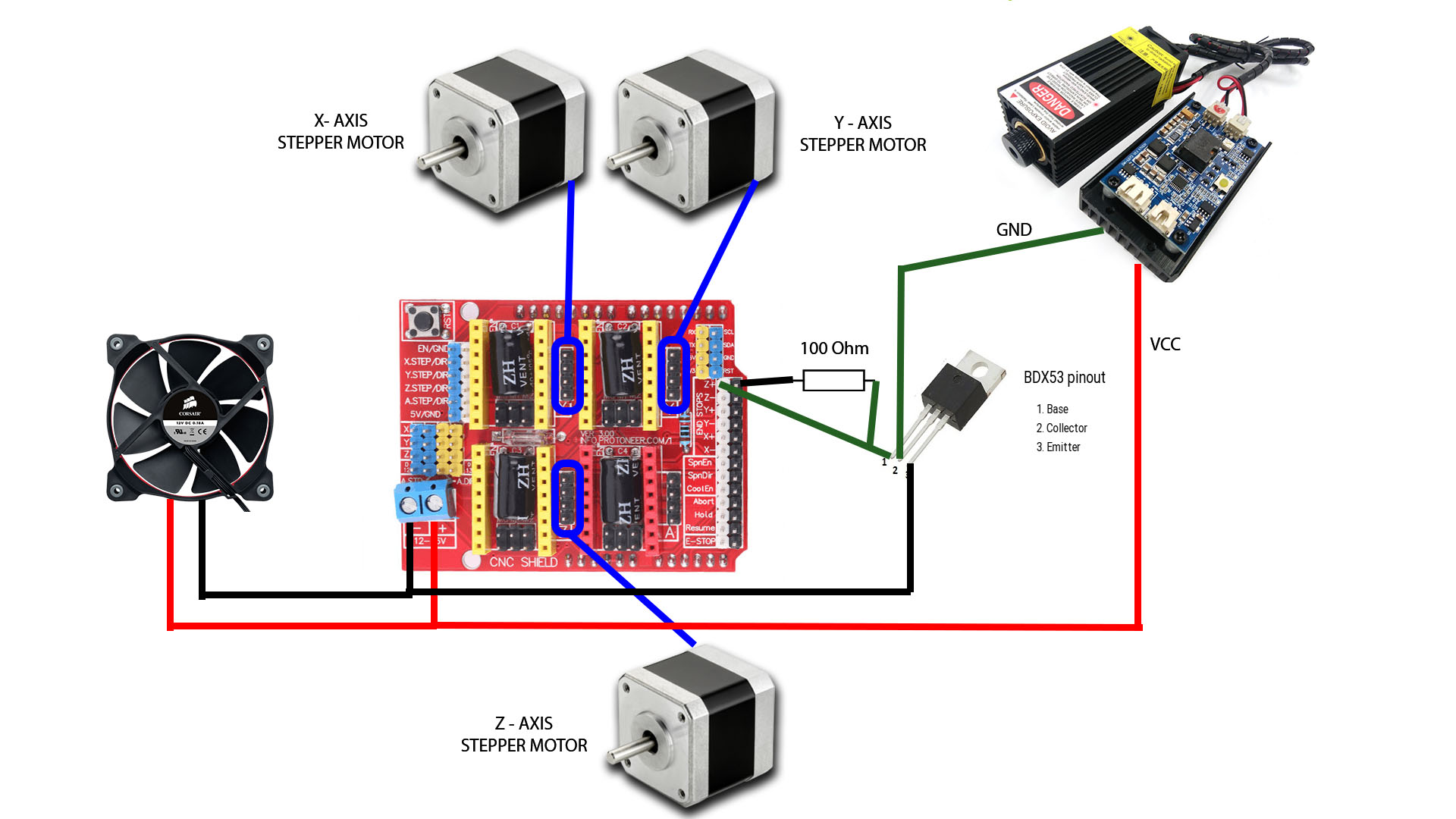
Step 4:CNC shield, Arduino Board, Drives, Software, Power source
In this step appears the CNC shield, Arduino, Drives, CNC softwares and Power Source
- to Install the CNC shield in the Arduino
It is neccesary previously to upload to the arduino this software:
- to Install the jumpers to work with micro stepping-this is a MUST in LASER mode
picture
- to Install the drivers and heat dissipators in the CNC shield
pictures
- to Calibrate the drivers
This is a key factor of successful of this project, you need to learn and apply properly these procedures.
I learnt a lot watching, again and again ,the videos from "el profe garcia", please check these videos :
Take care at this time you can cause damages in your Arduino UNO CNC shield and drives if you have the motors or the external power source connected to your Arduino UNO CNC shield during this process
- External Power source to feed the motors
The machine will have 4 motors-Nema 17, each motor are going to use 0.3Amps- 0.4 Amps, so you need to size properly this power source- I choose one 12V- 3A- 120VAC/60HZ and until today I haven't had any problem.
When you need to switch to a semi pro router for wood the NEMA17 motors are limited, so you will need NEMA23 heavy duty motors high torque and possibly screws no belts . However this machine can work with a mototool but you need to monitor temperature of the step motors. In this case the power source need to be upgraded to supply the amperes and voltage required for the new configuration.
Step 5:- Calibrate the stepper motors parameters
This is an assay and error iteration process- you need to enjoy and try to have fun identifying the behavior of the motors and machine. There are recommendations for the value of these parameter values but it is important to test as much as possible.
Be prepared to feel the happiness when your machine run by first time, and be prepared to have your machine death by weeks without any explanation-esoteric explanations are not valid always there are technical reasons for the fail state. In the last event you need to use methods to isolated, tracking and find fails in any machine.
Be sure , because if you do not calibrate the drivers in a good way, you will be frustrated in this project- do not go ahead if you are no 100% sure you can confirm this procedures was done right.
Be careful the motor's coils connections are one main source of fails of your machine, you need to be 100% sure the wiring is right and the sequence are going to produce the right output.
You need to install 3 jumpers if you want micro stepping- for laser and to use LASERGRBL software, or Lightburn this is a basic condition.
You need to install previously this software
- GRBL to Arduino software -uploaded to arduino
- Universal G code sender platform or LASERGRBL software- installed and running in your computer
Once you have these components you need to test and try parameters, please see this video:
The idea is to understand what is happening for each configuration and search for the best parameter of your machine-I really enjoy for days testing parameters.
Step 6:CNC X,Y tests
We are ready to use with limitations our CNC, I recommend this path to test X and Y axis with markers.
At this moment the machine builder are going to find a lot of mechanics deficiencies that turn into challenges to face, this is a way to learn how to solve these issues and I -as a builder- started to love more and more this machine.
Step 7:CNC X, Y,Z tests
Step 8:Emergency STOP Button and End Stop Switches
Over the test the machine some times going over the limits and parts , as a consequence the motors are suffering these forced and wrong operations. To prevent damages and people injuries we need to install
- Limit switches - for each axe
- Emergency Stop Button
- Others- fusibles/Interlocks/Current limitation
Tests are performed with pens or markers, however when you install a laser, a mototool or a spindle, risks of serious injuries are shifted. So please check carefully, at this point of the project, all the protections and interlocks you need to consider for install,test and operate properly.
In the case of use laser your risks of personal injuries and accidents are high so the path could be:
1- Pencils
2- Markers
3- Mototools
4- Laser
To working and testing with Laser you need a very serious risk assessment and googles, if you don't have skills to do that I recommend STOP here and request for help.
Step 9:To redesign and build the CNC's own parts-For this step you need better a laser with 90W of power, because the mechanical system for routing wood is weakness. Nema 17 motors have low torque and routing process need good power to work properly in different materials.
In this case we have a laser of 30W and wood thickness admited to cut is 3mm-5 mm afer variois passes. However with a good laser diode, the list of parts you can built to revamp the machines are:
-Motor support
-X axis sliders (2)
-Z axe
-Box for controls
-Chain for cables
-Box for power
-CNC Frame in wood light, expanded and collapsible
Step 10:Results as plotter, Laser, Router
Lizards
Dinosauries 3D
Animals for wall decoration:
Drawings working as plotter
Metal Engraving
Step 11:Lesson learnt and new machine design
This project is like to open a door for new initiatives, so when you reach this point you will be thinking in a lot of ideas for this machine.
Project budget is low and acceptable for a DIY CNC. You will have the temptation to spend more and more money in accessories &parts.
We are Pangeatech MakersCol - From Colombia LATAM

Comments
Please log in or sign up to comment.