After successfully trying to build my own mechanical keyboard using other people PCB design. I want to try to design my own keyboard but before I go there I want to start to design something simple. So I try to design a macro pad 1st.
My requirement for the macro pad are it need to be 4x4 switch to replace the numpad for my 60% keyboard.
Material and Component SelectionBy the time I am making this project we are in a chip crisis situation, so for this project I choose the RP2040 chip because its still in a stable stock situation. And because for this macro pad I don't need a lot of pins I choose the Xiao RP2040 for its size and easiness. Also the RP2040 already support a few keyboard firmware like PRK and KMK
The switch I am using for this project are Cherry MX based switch. There a bunch of 3rd party vendor that make these kind of switch.
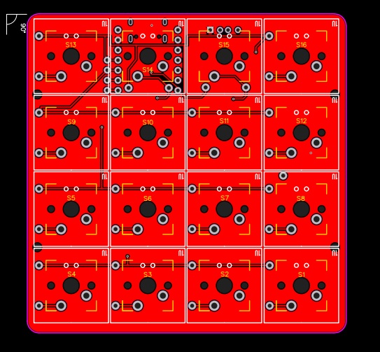
Designing the PCBI design the PCB using EASYEDA, there are a lot of samples that I can Learn. Following the footprint from the Xiao board I start to choose which pin become the columns and which pin become the rows
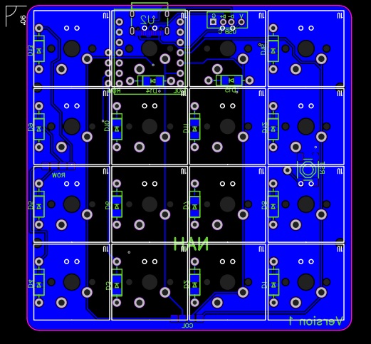
For the diode, because I cannot decide which footprint is better so make the diode footprint to support both PTH and SMD footprint.
even though this was made with the Xiao footprint in mind, I want the PCB to be also compatible with a few other microcontroller or dev board. So I add a USB C footprint and make 4 hole connected to the Vcc, GND, D+, and D- of the USB. the 4 hole next to the column is for the raspberry pi pico
and this is the final result
After I Finish designing the PCB Seeed Fusion was kind enough to sponsor this proof of concept for the prototypes for the keyboard development contest. Check out the link below for details: https://www.seeedstudio.com/seeed-fusion-diy-xiao-mechanical-keyboard-contest.html
After few email exchange and the PCB finally Arrive along with its components such as switches and the Xiao RP2040. It have a very nice quality for sure. Also for this project they offer the seeed fusion pcba service for two pcb, and two of my PCB already have the diode soldered already.
All I do next is put and solder the switches
This is the part where it get challenging for me because I never done this before. After a google search thankfully there is website that is dedicated to generate a custom case for mechanical keyboard.
After I input the the specification for my macro pad it generate the case nicely. But it still need a lot of adjustment, so I try to learn inkscape and edit the files there.
After the design is done, I took it to a local acrylic workshop and get it print there. And the 1st design is a failure because I miss a few millimeter for the mounting hole and the switch plate.
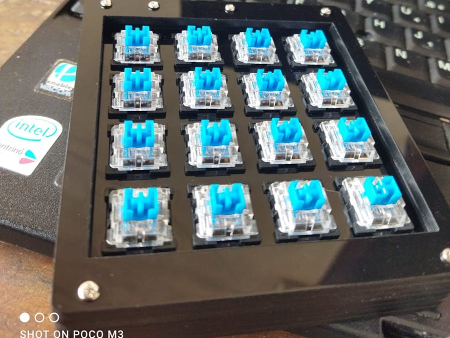
2nd design still failing but the 3rd one is a success, and this is the final product
There a few ready to use firmware for mechanical keyboard like the popular QMK and ZMK. But for this project I am gonna stick to python and since the RP2040 capable to run circuitpython so I am gonna use KMK firmware which based on circuitpython.
1st step you need to make sure that circuitpython is installed in the Xiao RP2040. It is a really simple process, just follow this guide from seeedstudio.
Go to KMK firmware github page and download/clone the repository. on the Copy the kmk folder directly to lib folder on the CIRCUITPY drive of the microcontroller
Next copy the boot.py file from the repo you just download to the root of the CIRCUITPY drive
Choose an IDE between mu editor or thonny editor to make the code for the keyboard. This time I am gonna use thonny. Open your serial port in thonny and we are ready to code the keyboard
Based on this picture below we already know which pins are row and which pins are column
just paste this code to the thonny IDE and save it as code.py
print("Starting")

import board
from kmk.hid import HIDModes
from kmk.kmk_keyboard import KMKKeyboard
from kmk.keys import KC
from kmk.scanners import DiodeOrientation

keyboard = KMKKeyboard()

keyboard.col_pins = (board.D6,board.D5,board.D4,board.D3,)
keyboard.row_pins = (board.D10,board.D9,board.D8,board.D7,)
keyboard.diode_orientation = DiodeOrientation.COL2ROW

keyboard.keymap = [
    [KC.A, KC.B, KC.C, KC.D,
     KC.E, KC.F, KC.G, KC.H,
     KC.I, KC.J, KC.K, KC.L,
     KC.M, KC.N, KC.O, KC.P,
     ]
]

if __name__ == '__main__':
    keyboard.go()
and you are good to go. If you want to change the keyboard function just change the content of keyboard.keymap list according to this keycode guide from KMK
ConclusionWith this project I learn a lot of new things in mechanical keyboard world and also Cad design.
I was planning to make the macropad wireless by using the XIAO BLE but somehow I misplace the battery connection and the Xiao BLE just failed on me because of my mistake. maybe in the future when get my hand on another Xiao BLE I will try to make the macropad wirelessly/
I wanna say Huge thank you to SeeedStudio for making this project possible and it was fun and great experience trying their awesome PCBA service which been very helpful regarding the components needed for this project


Comments
Please log in or sign up to comment.