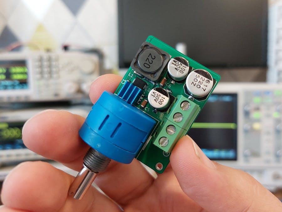
A DC-to-DC converter is one of the most commonly used circuits in electronics, especially in power supply applications. There are three major types of DC-to-DC converters (non-isolated): Buck, Boost, and Buck-Boost. Sometimes a buck converter is also called a step-down converter and a boost converter is also called a step-up converter.
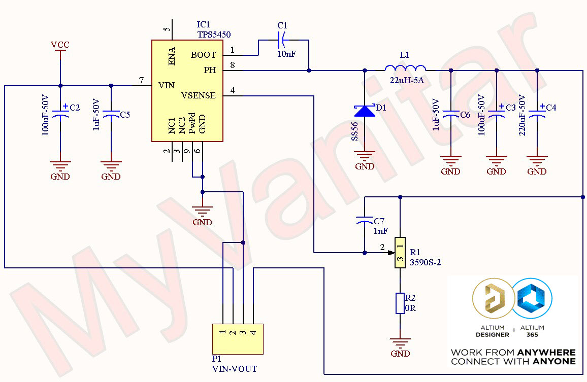
In this article/video, I introduce an adjustable 5A DC-to-DC converter circuit that uses an advanced chip, made by Texas Instruments, which is TPS5450. It’s a high-frequency and efficient buck converter chip that provides tight voltage regulation. I have followed several PCB design rules to ensure low noise, low EMI, and high stability of the output voltage.
To design the schematic and PCB, I used Altium Designer 23 and shared the project with my friends using Altium-365. The fast component search engine (Octopart) allowed me to quickly consider components’ information and also generate the BOM. To get high-quality fabricated boards, I sent the Gerber files to PCBWay and tested the circuit for output stability and noise, using a DC load, A multimeter, and an oscilloscope. Soon later, I will also perform the step-response test and demonstrate the results.
ReferencesMain: Download the Gerber or order 10Pcs high-quality boards
[1]: TPS5450: https://octopart.com/tps5450ddar-texas+instruments-7105511?r=sp
[2]: SS56: https://octopart.com/ss56bf-hf-comchip-107339894?r=sp
[3]: 3590-S2: https://octopart.com/3590s-2-502l-bourns-112621?r=sp
SpecificationsInput Voltage: 5.5V to 36V
Output Voltage: 1.22Vmin to 31Vmax (variable)
Output Current (continuous): 5A
Output Current (peak, short time): 6A
Maximum Output Drop: 22mV (5A load)
Output Noise: 14mVp-p (no load), 50mVp-p (5A load), 20MHz-BW


Comments
Please log in or sign up to comment.