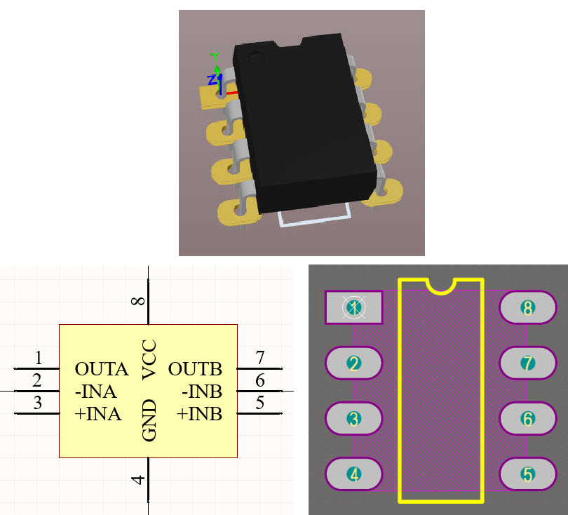
In this video, you will learn how to design/create a schematic symbol and a PCB footprint (a component library) in Altium designer and attach a 3D model to the footprint. Basically, you will create an integrated library and add the schematic symbol and the PCB footprint. Then you are ready to compile the library and use it. My selected component for this tutorial is the LM358 opamp, DIP8 package.
PCB Footprint, Schematic Symbol, 3D Model in Altium Designer
PCB Footprint, Schematic Symbol, 3D Model in Altium Designer

Read more


Comments
Please log in or sign up to comment.