Inrush current/Switch-ON surge is the maximal instantaneous input current drawn by an electrical device when first turned on. Inrush current is much higher than the load’s steady-state current and that’s the source of many problems such as fuse blowing up, load failure, load’s lifetime reduction, sparks at the switch contacts … etc. The figure below shows the inrush current phenomenon captured on the Siglent SDS1104X-E oscilloscope. The long spike is clear. In this article/video, I tried to address this problem with an easy, however an effective solution. I have introduced two circuits for both AC and DC loads.
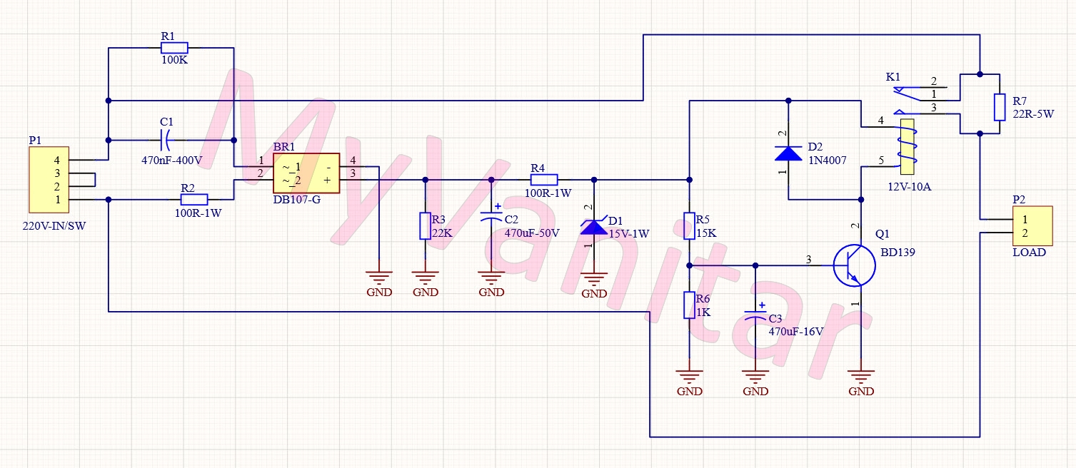
Figure-1 shows the schematic diagram of the device. P1 is used to connect the 220V-AC input and the ON/OFF switch to the circuit. C1 is used to reduce the AC voltage. The value of the C1 also determines the current handling rate for the transformer-less supply to be used by the rest of the circuit. In this application, 470nF was adequate. R1 discharges the C1 to avoid any unwanted high voltage shock when the user disconnects the device from the mains. R2 is a 1W resistor that has been used to limit the current.
BR1 is a DB107-G bridge rectifier [1] that has been used to convert the AC voltage to DC. C2 reduces the ripple and R3 discharges the C2 at Switch-OFF. Also, it provides a minimum load to keep the rectified voltage at a reasonable level. R4 reduces the voltage and limits the current for the rest of the circuit. D1 is a 15V Zener diode and has been used to limit the voltage below 15V. C3, R5, and R6 build a timer network for the relay. It means it makes a delay for the relay activation. The R6 value is essential, it should not be too low to drop the voltage too much and it should not be too high to reduce the network response time. 1K provided a satisfactory discharge rate for relatively high ON/OFF switching speed. With my experiments, this network provides enough delay and response time, of course, you are free to modify them based on your applications.
Q1 is the NPN BD139 [2] transistor to activate/deactivate the relay. D2 protects the Q1 from the relay’s inductor reverse currents. R7 is a 5W series resistor that limits the turn ON inrush current. After a short delay, the relay does short circuit the resistor, and the full power applies to the load. The value of the R7 has been set to 27R. You can modify it depending on your load or application.
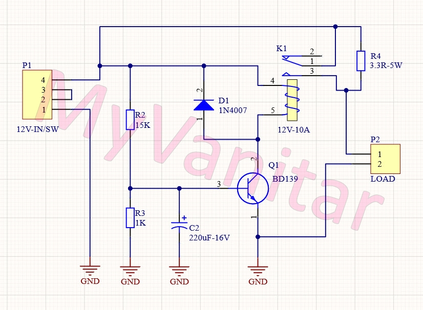
DC Soft StarterFigure 2 shows the schematic diagram of the DC soft starter. It is a simpler version of the AC soft starter with some minor modifications.
P1 is used to connect the 12V supply and the ON/OFF switch to the board. R2, R3, and C2 make the delay network for the relay. R4 is the current limiting resistor. The same as the AC soft starter, you are free to modify the delay network and R4 values for your specific load or application.
PCB LayoutFigure 3 shows the PCB layout of the AC soft starter. All component packages are DIP. The board is a single layer and pretty easy to build.
Figure 4 shows the PCB layout of the DC soft starter. The same as above, all component packages are DIP, and the board is a single layer.
For both designs, I used the SamacSys schematic symbols and PCB footprints. Specifically, for the DB107 [3] and BD139 [4]. These libraries are free and follow industrial IPC standards. I used Altium Designer CAD software, so I used the SamacSys Altium Plugin [5] (Figure 5).
Figure 6 shows a 3D view of the AC soft starter and figure 7 shows a 3D view of the DC soft starter.
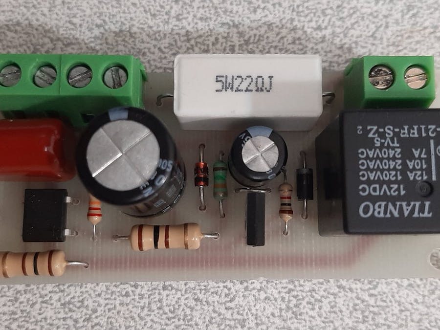
Figure 8 shows the assembled AC soft starter board and figure 9 shows the assembled DC soft starter.
Figure 10 shows the wiring diagram of the AC soft starter and figure 11 shows the wiring diagram of the DC soft starter.
Article:https://www.pcbway.com/blog/technology/Inrush_Current_Limiter__Soft_Starter__for_AC_DC_Loads.html
[1] DB107 Datasheet: https://www.diodes.com/assets/Datasheets/products_inactive_data/ds21211_R5.pdf
[2] BD139 Datasheet: https://www.onsemi.com/pub/Collateral/BD139-D.PDF
[3] DB107 Schematic Symbol and PCB Footprint: https://componentsearchengine.com/part.php?partID=771938
[4] BD139 Schematic Symbol and PCB Footprint: https://componentsearchengine.com/part.php?partID=971726
[5] CAD Plugins: https://www.samacsys.com/library-loader-help


Comments
Please log in or sign up to comment.