

Hardware components | ||||||
_ztBMuBhMHo.jpg?auto=compress%2Cformat&w=48&h=48&fit=fill&bg=ffffff) |
| × | 1 | |||
| × | 1 | ||||
| × | 1 | ||||
 |
| × | 1 | |||
| × | 1 | ||||
 |
| × | 1 | |||
 |
| × | 1 | |||
| × | 1 | ||||
 |
| × | 1 | |||
| × | 1 | ||||
 |
| × | 6 | |||
 |
| × | 1 | |||
 |
| × | 1 | |||
 |
| × | 2 | |||
 |
| × | 3 | |||
 |
| × | 1 | |||
Software apps and online services | ||||||
 |
| |||||
 |
| |||||
Hand tools and fabrication machines | ||||||
 |
| |||||
 |
| |||||
| ||||||
| ||||||
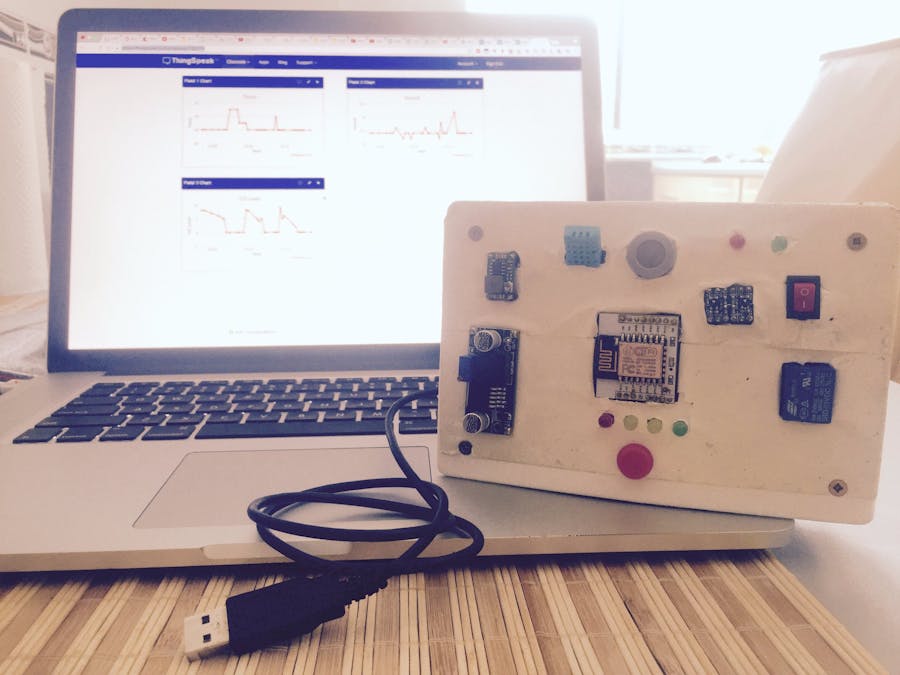
This project started off as a final assessment homework for an university course I've followed this year, but proved out to be a really fun and practical way of learning new and interesting things about wireless communication and microcontrollers in general.
The main idea:The core of this project is an Arduino Uno developing board which gathers data from two sensors:
- DHT 11 - which is used for measuring temperature and humidity levels
- MQ-7 - which is used for measuring the CO level in the air (ppm)
The data received from the sensors is then sent to www.thingspeak.com by using an ESP8266 12-E Wireless Module.
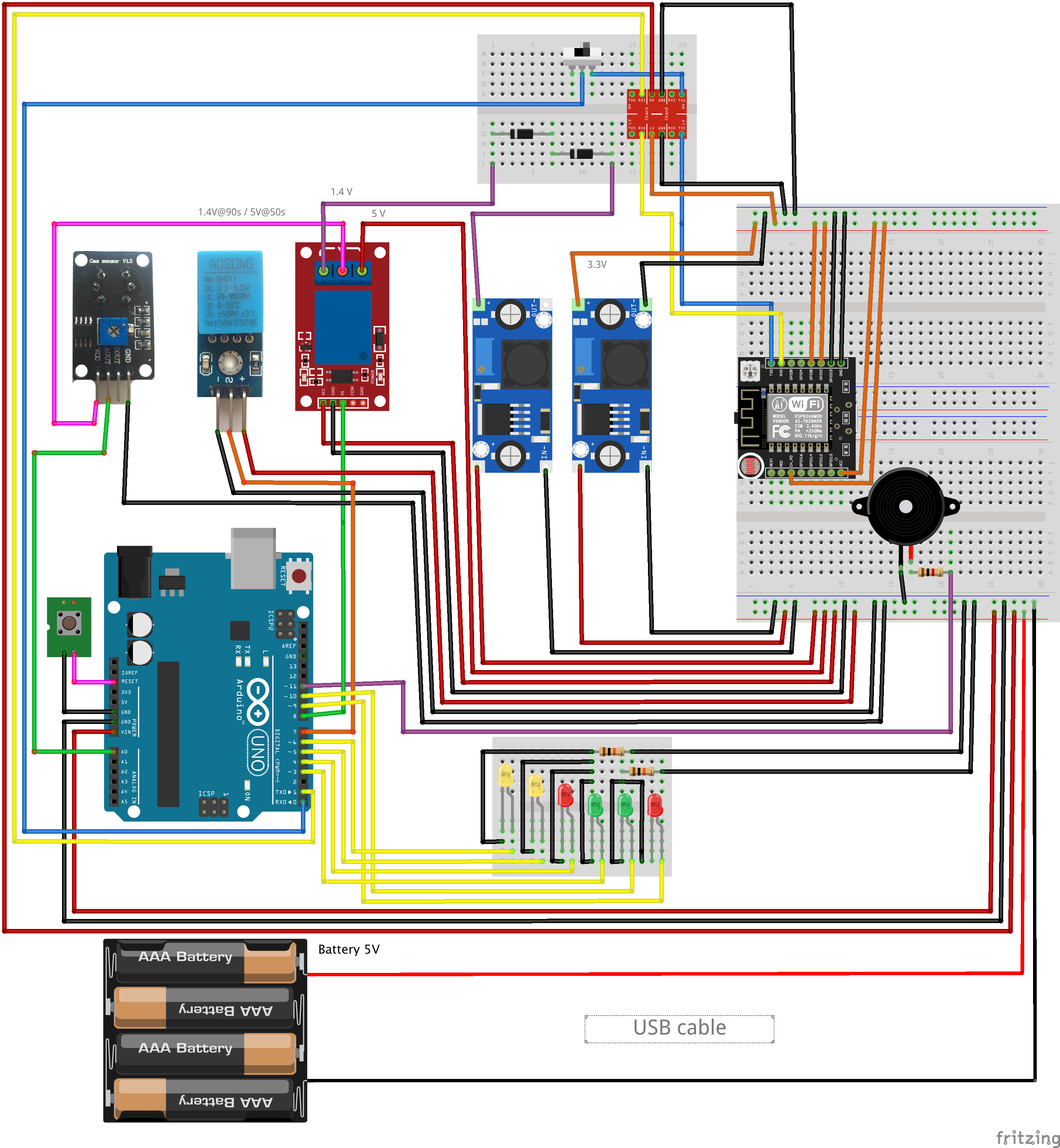
The components and their role:M1201 step down buck converter (#2)
This component is needed to step down the voltage from 5V to 1.4V. The 1.4V are then used to power up the MQ-7 gas sensor for a period of 90s, the so called "reading period". (check MQ-7 datasheet for more info on the operation principle)
Note: The one that I had couldn't go down to 1.4V (although it should have) so I've used 2 more diodes to lower the voltage (check the schematics)
Mini-360 step down buck converter (#3)
This component is needed to step down the voltage from 5V to 3.3V. You can as well see it as the main 3.3V power supply in the system. The 3.3V are used to power up the ESP8266 12-E Wi-Fi module, as well as the low side of the logic level shifter.
- The ESP8266 12-E is a Wi-Fi module which is powered at 3.3V, NOT 5V. Powering it at 5V will permanently damage the module!
- The ESP8266 draws more than 200mA of current while operating and sending values to the web server. Powering it from Arduino's 3.3V power pin would be a big mistake as Arduino cannot provide that much current, thus making the Wi-Fi module unstable.
SRD-05VDC-SL-C 5V 1 Channel Relay Module(#8)
This relay is directly connected on the powering line of the MQ-7 CO gas sensor and has the role of cycling between 1.4V for 90S and 5V for 60s. Why so? Well according to the MQ-7 datasheet you have to heat up the sensor for 90s@5V. Only after the heating cycle you can read the sensor values for the next 60s@1.4V.
Note: See the MQ-7 datasheet for mor info on this
Logic level shifter 5V - 3.3V (#7)
Since the Arduino Uno runs at 5V and the ESP8266 12-E runs at 3.3V the logic levels are quite different between the two components. Thus, when trying to "speak" with the ESP8266 by using the RX,TX (serial communication) ports on the Arduino Uno we need a logic level shifter to do so. This component does exactly what we need: shifts the logic levels from 5V to 3.3V.
- Check the image (fig. 1) bellow for a visual representation of the different logic levels.
- Same thing could also be done way cheaper by directly connecting the RX line between the two components, while using a voltage divider on the TX line of the Arduino Uno. For more info on this check the following link: http://jamesreubenknowles.com/level-shifting-stragety-experments-1741
Wi-Fi ESP8266 E-12 Wi-Fi module (#6)
I guess it's pretty obvious what this part is used for and that's connecting to a local Wi-Fi network (preconfigured in the source code) and sending the sensor data to www.thingspeak.com
On/Off Switch (#10)
It seems that one cannot upload a new source code file on the Arduino Uno while having the TX pin connected to another component. If you try to do so you would get a lot of errors in Arduino IDE. While uploading a new sketch the TX pin should be "floating". To do so, I've used a on/off switch to disconnect the TX line from the ESP8266 whenever I want to upload an new code on the board. (check schematics down bellow)
MQ-7 Gas Sensor (#5)
Used for reading the CO level in the air. The value provided is measured in ppm.
- As stated earlier check the datasheet to see the working principle. The sensor needs to be powered for 90s@5v, time during which no reading is done, and 60s@1.4V, time which represents the reading period.
- Check the datasheet for info on calibrating the sensor.
Reset button (#9)
Since the hole wiring will be hidden inside a box a the end of this project, with the Arduino Uno stuck with hot glue at the bottom of box, uploading a new sketch on the board it would pose quite a problem when it comes to physically reseting the board without opening the box. To solve this issue we would need an external reset button. That's exactly what this big red button does. It resets the board.
The LED's (#9)
- 11 - general error indicator (for debugging the error we would need to connect the board to a pc and check the Serial Monitor Interface in Arduino IDE for the error message)
- 12 - signals the presence/absence of the ESP8266 in the current system
- 13 - signals if ESP8266 is connected/not connected to the local network
- 14 - signals sending sensor data tot thingspeak.com
- 15 - blinks whenever the MQ-7 is heating
- 16 - blinks whenever Arduino Uno reads data from sensors
The Buzzer
Whenever the CO level read from the MQ-7 gas sensor exceeds a certain value hardcoded in the code, an alarm will be triggered by using the buzzer.
Software requirements:In order to see the value of sensor data, we will need a private channel on thingspeak.com. We will also need Arduino IDE to write/upload the code for Arduino Uno.
List of software requirements:
- Private channel on Thingspeak.com and
- Arduino IDE (Preferably latest version).
You can download latest version of Arduino IDE from arduino.cc.
In order for the sketch to work we will also need the DHT11 library which you can download in the attachment section down bellow. For a step by step tutorial on how to add this library to Arduino IDE check the following link: https://www.arduino.cc/en/Guide/Libraries
Now lets create a private channel on thingspeak.com
Creating private channel on Thingspeak.comTo make a private channel on thingspeak.com follow these steps:
- Open your web browser and go to thingspeak.com and click on 'Sign Up' tab in right top corner, (Image no.1)
- Fill in the details and click on 'Create account', (Image no.2)
- Now click on 'New Channel' tab, (Image no.3)
- Again fill in details for channel and enable 4 fields (as we will be sending 4 sensor values), scroll down and click on 'Save Channel' tab, (Image no.4/5)
- On this page click on 'API Keys' tab and note down your 'Write API Key'.
That's all folks, now you have your private ThingSpeak channel. Now lets put all electronics component together.
The CodeThe code for Portable weather station is quite simple. I have commented code properly for ease of portability. Before you burn the code take care of following things.
- Make sure that all libraries are installed,
- Replace hyphens (--------) with SSID of your access point (wifi router) in line 14 of the code,
- Replace hyphens (--------) with PASSWORD of your wifi network in line 15 of the code,
- Replace hyphens (--------) with your ThingSpeak's private channel write API key in line 17 and
- While uploading the code to the Arduino make sure that the on/off switch on the TX line is set to "off" so that you can upload the code
Now that we have our hardware and software in place, only thing remaining is packaging.
The logicIf you find the code pretty difficult to understand take a look on the logic diagram down bellow:
Down bellow you are going to find some useful photos taken while I was preparing the enclosure for the system. Make sure you have the tools required to make a box like the one bellow (elecrtic file, soldering iron, hot glue gun...)
- As you can see in the third image above I've used some generic "mother" type pins soldered together for providing power/ground to the components of the system. I've then hot glue the piece to the side panel of the box, inside of it.
You can check the results of this project by clicking on the following link which should redirect you to the public view of my thingspeak channel: https://thingspeak.com/channels/152176
- Sometimes some parts of the system went unresponsive due to poor contact on the breadboard. If the ESP8266 becomes unresponsive out of a sudden, first thing I would suggest doing would be to check the connections once again
- If you see a lot of garbage in the Serial Monitor console make sure the baud rate in the console is set accordingly with the ESP8266 settings.
For more info on changing the baud rate of the Serial Montior console check the following link: https://learn.adafruit.com/adafruit-arduino-lesson-5-the-serial-monitor/other-things-to-do
For more info on changing the baud rate setting of the ESP8266 check the following link: http://www.esp8266.com/viewtopic.php?f=13&t=718
- Make sure you calibrate the MQ-7 sensor correctly as if not you would receive some big measurement errors
For more info on that check the following link: http://forum.arduino.cc/index.php?topic=55799.msg399839#msg399839
Future projects tips- DHT11 isn't quite precise, in the sense that it can give random errors. A DHT22 sensor would prove much more accurate, but it is also a little bit more expensive than the DHT11
- ESP8266 proved to be a little bit unstable during the development phase. A ESP32 or a NodeMCU board might be better for a future project


_3u05Tpwasz.png?auto=compress%2Cformat&w=40&h=40&fit=fillmax&bg=fff&dpr=2)


Comments