


Introduction.
NOTE: this article is a condensed "recipe" version of the original series spanning four parts available here:
The source of the project is hosted in the azure-veneziano GitHub repository.
This is an example of a very basic a telemetry project which may be classified as a classic “Internet of Things” (IoT) application.
The goal is to use the LinkIt ONE board as sensor data collector, and get it to send those data on the Microsoft Azure cloud infrastucture, which offers several useful services for free. For sake of semplicity, I'll show only how to interface the board to the cloud: any further data elaboration and presentation is off this article.
Setup the mobile service
To set up the Microsoft Azure Mobile Services isn't difficult at all, and it's completely free. You just need to register and follow some easy steps.
I suggest to read the walkthrough here.
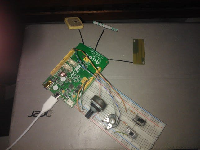
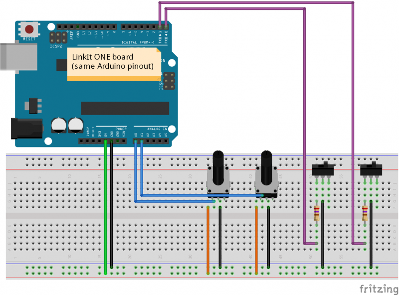
The hardware.
The sensors can be whatever you want. I used a couple of potentiometers and a couple of switches, but you may use any other source of data. At the moment, there's no support for "outgoing" data, that is data originated by the cloud and moved to the board (e.g. lights, motors, relays, etc).
Since the integrated GPS, I also used it to track the board position, as it were another data input.
The software.
The software running in the board is very simple. It can be structured as follows:
- the main application, as the primary logic of the device;
- some hardware port wrappers as data-capturing helpers;
- a HTTP-client optimized for Azure-mobile data exchange;
- a JSON DOM with serialization/deserialization capabilities;
The JSON library comes from Benoît Blanchon, who made a very cool job.
The library is well written, in my opinion, but you should bear in mind that the Benoît target was the “real” Arduino, as very poor on resources (and language features).
That is, the LinkIt board is a 32-bit ARM core, thus the memory usage is way higher than what described in the library Wiki.
For the HTTP client, I chose this library.
It’s a minimalistic HTTP composer and parser, but way enough for what any hobby project requires. It comes also with the BASIC authentication.
The aims of the port wrappers are double:
- yield a better abstraction over a generic input port;
- manage the “has-changed” flag, especially for non-discrete values as the analogs.
The class exposes the “Sample” method to capture the ADC value (Read method). The purpose is similar to a classic Sample-and-Hold structure, but there is a compare algorithm which detect the new value’s variation.
Basically, a “tolerance” parameter (normalized) has to be defined for the port (default is 5%). When a new sample is performed, its value is compared in reference to the “old value”, plus the tolerance-window around the old-value itself. When the new value falls outside the window, the official port’s value is marked as “changed”, and the old-value replaced with the new one.
This trick is very useful, because allows to avoid useless (and false) changes of the value. Even a little noise on the power rail can produce a small instability over the ADC nominal sampled value. However, we need just a “concrete” variation.
There’s also a “false-wrapper” because it does NOT wrap any port, but it WORKS as it were a standard port. The benefit become from the interfaces abstraction.
In order to PRODUCE data overtime for the demo, I wanted something automatic but also “well-known”. I may have used a random-number generator, but…how to detect an error or a wrong sequence over a random stream of numbers? Better to rely on a perfectly shaped wave, being periodic, so I can easily check the correct order of the samples on the server, but any missing/multiple datum as well.
As a periodic signal you can choose whatever you want. A sine is maybe the most famous periodic wave, but the goal is testing the system, not having something nice to see. A simple “triangle-wave” generator, is just a linear ramp rising-then-falling, indefinitely.
Here is how a triangle-wave looks in a scope (it’s a 100 Hz, just to give an idea).
Of course, I may have used a normal bench wave-generator as a physical signal source, as in the snapshot right above. That would have been more realistic, but the expected wave period would have been too short (i.e. too fast) and the “changes” with consequent message upload too frequent. A software-based signal generator is well suited for very-long periods, like many minutes.
The main application
As the Azure Mobile Services offer, there are two kind of APIs which can be called: table- (Database) and custom-API-operations. Again, I’ll detail those features on the next article.
The key-role is for the OperateCore method, which is a private entry-point for both the table- and the custom-API-requests. All Azure needs is some special HTTP-headers, which should contain the identification keys for gaining access to the platform.
The request’s content is just a JSON document, that is simple plain-text.
After the initialization, the program runs in a loop forever, and about every second all the ports are sampled. Upon any “concrete” variation, a JSON message is wrapped up with the new values, then sent to the server.
The led toggling is just a visual heartbeat-monitor.
The message schema
In my mind, there should be more than just a single board. Better: a more realistic system should connect several devices, even different from each other. Then, each device should provide its own data, and all the data incoming into the server would compose a big-bunch of “variables”.
For this reason, it’s important to distinguish the data originating source, and a kind of “device-identification”, unique in the system, is included in every message.
Moreover, I’d think that the set of variables exposed by a device could be changed any time. For example, I may add some new sensors, re-arrange the input ports, or even adjust some data type. All that means the “configuration is changed”, and the server should be informed about that. That’s because there’s a “version-identification” as well.
Then are the real sensors data. It’s just an array of Javascript objects, each one providing the port (sensor) name and its value.
However, the array will include only the port marked as “changed”. This trick yields at least two advantages:
- the message length carries only the useful data;
- the approach is rather “loose-coupled”: the server synchronizes automatically.
Here is the initial message, which always carries all the values:
 {
  "devId": "01234567",
  "ver": 987654321,
  "data": [
    {
      "name": "Switch0",
      "value": true
    },
    {
      "name": "Switch1",
      "value": true
    },
    {
      "name": "Ramp20min",
      "value": 0
    },
    {
      "name": "Ramp30min",
      "value": 50
    },
    {
      "name": "Analog0",
      "value": 0.073260073260073
    },
    {
      "name": "Analog1",
      "value": 45.079365079365
    }
  ]
}
After that, we can adjust the trimpots and the switches in order to produce a “change”. Upon any of the detected changes, a message is composed and issued:
Single change
 {
  "devId": "01234567",
  "ver": 987654321,
  "data": [
    {
      "name": "Analog1",
      "value": 52.503052503053
    }
  ]
}
Multiple changes
 {
  "devId": "01234567",
  "ver": 987654321,
  "data": [
    {
      "name": "Switch1",
      "value": false
    },
    {
      "name": "Analog1",
      "value": 75.946275946276
    }
  ]
} "devId": "01234567",
  "ver": 987654321,
  "data": [
    {
      "name": "Switch1",
      "value": false
    },
    {
      "name": "Analog1",
      "value": 75.946275946276
    }
  ]
}


Comments
Please log in or sign up to comment.