The article explores the integration of the ESP32 microcontroller with the Stepper Motor 28BYJ-48 and the ULN2003 Motor Driver. Stepper motors offer precise positioning and rotation, making them ideal for various applications. The 28BYJ-48 stepper motor is cost-effective and compact, while the ULN2003 Motor Driver serves as a reliable intermediary between the ESP32 and the motor.
The article provides insights into the setup process, code implementation, and potential applications, such as robotics, CNC machines, camera gimbals, and automation systems. By combining the ESP32 with this stepper motor driver duo, hobbyists, engineers, and innovators can explore new possibilities for precise motion control in embedded systems and IoT devices.
JLCPCB is the foremost PCB prototype & manufacturing company in China, providing us with the best service we have ever experienced regarding (Quality, Price Service & Time).
What is 28BYJ-48 Stepper Motor?The 28BYJ-48 is a commonly used stepper motor known for its low cost, compact size, and ease of use. It is widely used in various hobbyist and DIY projects, especially in the Arduino and Raspberry Pi communities. This type of stepper motor falls under the category of unipolar stepper motors.
The 28BYJ-48 stepper motor has several distinctive features:
- Step Resolution: It has a step angle of 5.625 degrees, which means it requires 64 steps to complete a full 360-degree revolution.
- Gear Reduction: The motor comes with a built-in reduction gear train. In most cases, it has a gear ratio of 64:1. This means that for every 64 steps the motor takes, the output shaft completes one full rotation.
- Voltage and Current: The 28BYJ-48 is designed to operate at a relatively low voltage, typically around 5V. It is optimized for low-power applications. The current rating is usually around 200-300mA per coil.
- Control: The motor is controlled using a simple sequence of high and low logic signals on its four coils. It is generally driven using motor driver modules like the ULN2003, which simplifies interfacing with microcontrollers.
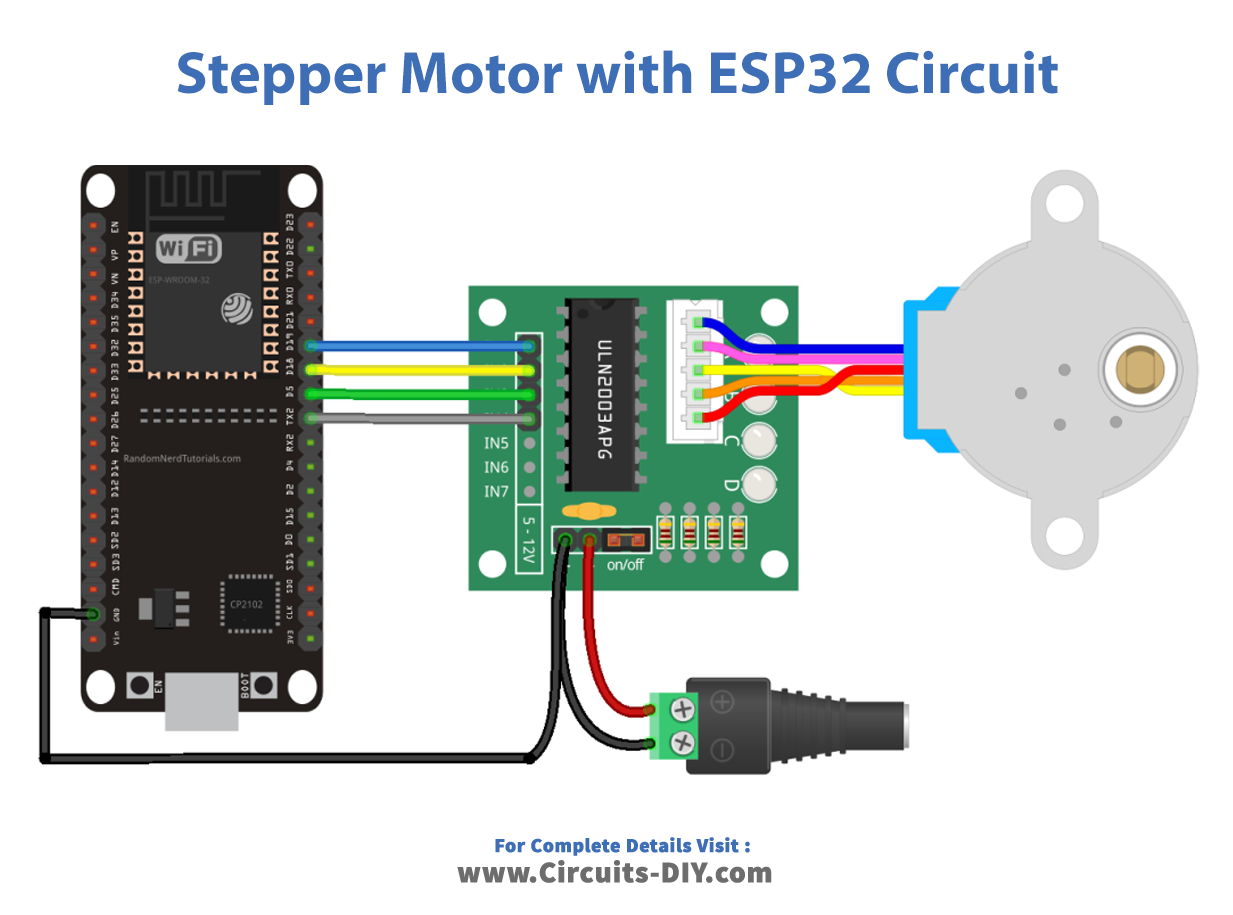
Make connections according to the circuit diagram given below.
First, you need to Download Arduino IDE Software from its official website Arduino. Here is a simple step-by-step guide on “How to install Arduino IDE“.
Installing the ESP32 Board in Arduino IDEAfter the Installation of Arduino IDE, There’s an add-on that allows you to program the ESP32 using the Arduino IDE. Here is a simple guide on “How to Install ESP32 on Arduino IDE“.
Installing LibrariesBefore you start uploading a code, download and unzip the following libraries at /Program Files(x86)/Arduino/Libraries (default), in order to use the sensor with the ESP32 board. Here is a simple step-by-step guide on “How to Add Libraries in Arduino IDE“.
CodeNow copy the following code and upload it to Arduino IDE Software.
#include <Stepper.h>

const int stepsPerRevolution = 2048;  // change this to fit the number of steps per revolution

// ULN2003 Motor Driver Pins
#define IN1 19
#define IN2 18
#define IN3 5
#define IN4 17

// initialize the stepper library
Stepper myStepper(stepsPerRevolution, IN1, IN3, IN2, IN4);

void setup() {
  // set the speed at 5 rpm
  myStepper.setSpeed(5);
  // initialize the serial port
  Serial.begin(115200);
}

void loop() {
  // step one revolution in one direction:
  Serial.println("clockwise");
  myStepper.step(stepsPerRevolution);
  delay(1000);

  // step one revolution in the other direction:
  Serial.println("counterclockwise");
  myStepper.step(-stepsPerRevolution);
  delay(1000);
}This code controls a stepper motor using an Arduino and the ULN2003 motor driver module. A stepper motor moves in discrete steps and its precise control is achieved by energizing coils in a specific sequence. The code utilizes the Stepper library, which simplifies the motor control process.
The stepper motor used in this example is configured to have 2048 steps per revolution. The motor driver module is connected to four pins on the Arduino: IN1, IN2, IN3, and IN4. These pins determine the current flow through the coils of the stepper motor, causing it to step in a particular direction.
In the setup() function, the code configures the Stepper library by specifying the number of steps per revolution and the four pins connected to the motor driver. Additionally, the motor’s speed is set to 5 revolutions per minute (rpm). The Serial communication is initialized to a baud rate of 115200 to display messages on the serial monitor.
In the loop() function, the code performs the following steps in an infinite loop:
- The stepper motor is rotated one revolution in the clockwise direction by calling myStepper.step(stepsPerRevolution).
- A 1-second delay is introduced using delay(1000).
- The stepper motor is then rotated one revolution in the counterclockwise direction by calling myStepper.step(-stepsPerRevolution).
- Another 1-second delay is introduced.
The serial monitor is used to display messages indicating the direction of rotation for each step, showing “clockwise” and “counterclockwise” alternately.
Overall, this code allows the stepper motor to rotate continuously back and forth, with a 1-second pause between each revolution and provides simple visual feedback of the direction of rotation through the serial monitor.
ApplicationsDue to its affordability, simplicity, and ease of use, the 28BYJ-48 stepper motor is widely used in various projects, such as robotic arms, camera sliders, automated curtains, and other motion control applications that require accurate and repeatable movements.
ConclusionThe 28BYJ-48 stepper motor is a cost-effective and versatile motor widely utilized in hobbyist projects for its ease of use and precise control. Its compact size and built-in gear reduction make it suitable for various applications, presenting an ideal choice for motion control in DIY electronics and automation projects.


Comments