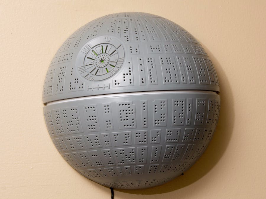
My son received a Death Star nightlight as a gift. He's a huge Star Wars geek (who isn't?), so it's one of his favorite things in the whole world. It's basically a large plastic hemisphere riddled with holes that hangs on a wall. Inside are 4 bright white LED's (the sort you'd find on LED strip lights) that shine out through the many, many holes. There's a slider switch on the outside to turn it on and off. Out of the box it was powered by 3 AA batteries. Not for long....
_________________________________________________________
OverviewThis thing turned out to be as hungry for power as the Emperor and Lord Vader combined! Between its high consumption rate and my son's propensity to forget to turn it off in the morning, it was going through a set of batteries every 5 days or so. Yikes!
Thus our first ever hack was launched!
First order of business was to mod the Death Star itself to run on wall power. Once that was complete, it seemed a shame to leave it controlled by the on-board slider switch. Surely the Empire would have sprung for something more high-tech! A wireless control of some sort was in order.
DetailsWall Power
Converting to wall power was fairly straightforward. I found a 4.5v wall wart DC adapter on Amazon. I purchased a panel mount DC jack from the local Microcenter. Mount the jack inside the battery compartment, unsolder the wires leading to/from the battery compartment, resolder them to the DC jack, plug in the wall wart, and et voila! No more batteries.
Wireless Remote
After considering several options, we settled on Adafruit's RF keyfob and one of their RF receivers. This combo was perfect for our needs and wouldn't require any coding. It was pretty much plug-and-play. Pretty much.
We breadboarded our initial design, connecting one of the output pins of the RF receiver to an LED. It worked perfectly. Push button A on the key fob, the LED lit up. Push button A again and it extinguished. Brilliant!
Not :(
Once we wired our components to the Death Star itself, it turned out the RF receiver wasn't putting out enough juice to power the Death Star. Drat! I measured the output of the receiver's pin and it was significantly less than the 4.5 volts our night light wanted.
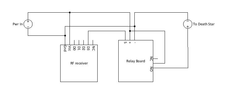
The fix wasn't too bad - add a relay to the equation. The output pin of the RF receiver was sufficient to trigger the relay. The relay would transfer all 4.5v from the input power to the Death Star. Problem solved!
Power Distribution
When all was said and done, we had 4 points needing roughly 4.5-5v of power input:
- The RF receiver (+ and -)
- The relay board (+ and -)
- The relay itself (+ only)
- The output to the Death Star (- from input power, + from relay)
Our first attempt involved a couple of push-in wire connectors from the local home improvement center. That worked ok on the bench, but when it was time to stuff everything into a project box, well, it didn't work so well. Connections weren't as tight as they needed to be resulting in flaky connections. Also, the connectors themselves were a little bulky.
So, I fired up Eagle and drew up a small, simple power distribution PCB. I designed it to use 4 JST PH jacks, but 2 pins of regular old male header would work as well. I sent the Eagle file off to OSH Park to have our boards manufactured. Six boards cost less than $8.00 It did take 10 days to receive them, but it was worth the wait!
Now our power distribution is more compact, connections are more secure, and we can easily disassemble our project should the need arise.
Enclosure
We wanted to enclose all the components that comprised our wireless remote control, apart from the fob, in a small project box. It'd keep everything well protected and look tidier than having a jumble of electronic bits dangling about.
We found a perfectly sized, rectangular project box at Microcenter. We mounted a DC jack in each end of the box. One would receive power from a wall wart DC adapter. The other would deliver switched power to the Death Star. We fabbed a 2-wire cable with a male DC barrel connector at both ends to connect our project box to the Death Star.
Future Enhancements
- Voice control
- IoT-ify it.
Step 1 - Mod the Death Star
The first step was to connect the Death Star to shore power.
- Remove the batteries
- Drill a hole in the wall of the battery compartment.
- Fill the hole with DC power jack
- Un-solder the 2 wires that are connected to the battery compartment
- Re-solder them to the DC power jack. Connect positive to the center post, negative to the outer ring.
Step 2 - Prep the project box
The next step was to prepare the project box. This simply involved using a step-bit and cordless drill to punch 2 holes in our enclosure. The size of these holes need to be perfect fit for the panel-mount DC jacks, so we went slow and easy with the drill, working our way up until the hole was the perfect size.
Step 3 - Assemble Power Distribution Board
Next, we soldered 2 JST PH jacks and 2 2-pin headers to our custom power distribution board. We had to pay attention that the +/- orientation of the JST jacks matched. There's a notch in the jack that mates to the corresponding JST PH connector which means there's only 1 way to plug the connector into the jack. We don't want our power cross-wired, so the notch on both jacks has to face the same direction. Yeah, the silkscreen on the PCB indicates where to put the notches, but the jacks fit into the holes either way, so you still have to pay attention!
I designed the board to hold 4 JST jacks, however, for this project, it was more convenient to use just 2 JST jacks and 2 2-pin headers. When I designed the board, it looked like the spacing between the pins of the jack was identical to the spacing of standard male header pins, so I figured it be easy to use either connector. It turns out, the JST jack pins are a tiny bit closer together than header pins. No problem, I just pinched the pins of the header together to bend them just a tiny bit and they fit right in the PCB.
Step 4 - Assemble Wire Harnesses
I originally purchased a set of Dupont connectors and housings and a crimper. After many failed attempts to crimp female Dupont connectors to custom length wires, I went looking for a pre-assembled, custom option. I didn't find anything truly custom, but I did find an online vendor, Pololu, that offers pre-crimped wires in various colors at multiple lengths. Close enough!
Custom wire harnesses are now a simple matter of grabbing the wires I need and inserting the ends into the appropriate housing. For this project we needed the following harnesses:
- 2-pin from power distribution to RF Receiver
- 3-pin from relay board - 2 wires to power distribution, 1 to RF receiver
We also use a pair of pre-assembled, 2-wire, JST PH lead wires. One gets soldered to the input DC jack and plugged into the power distribution board. The other is also plugged into the power distribution board - the positive wire is inserted into the screw terminal of the relay. The negative wire is soldered to the output DC jack.
Step 5 - Solder wires to DC Jacks
Ok, not much soldering in this project, and it's pretty straightforward. Just need to make sure to get the red wire connected to the center pin of the jack (+) and the black wire connected to the outer (-). Magic smoke may appear if you get this backwards (DAMHIKT).
Both wires of one of the JST PH lead wires are soldered to the input jack. On the output side, the black wire of the other JST PH lead is soldered to the jack. Then a single, red jumper wire (we used bell wire for this) is soldered to the output jack. The other end of this wire will be connected to the screw terminal of the relay.
Step 6 - Secure Components to Project Box
Having bits and pieces just rattling around inside the enclosure felt kind of amateurish. Sort of like leaving an exhaust port exposed where those pesky rebels could find it. It certainly doesn't help the integrity of our connections either! So we wanted to secure the RF receiver, the relay board and the power distribution PCB to the bottom of the project box.
Our relay board had holes where we could've used basic stand-offs to screw it to the bottom. However, neither the RF receiver nor the power distribution board had such amenities. So we opted to use padded, double-sided tape. A little cheesy, and probably wouldn't hold up to a lot of handling, but once in situ, it shouldn't see much touching and fondling.
Step 7 - Plug it all Together!
Time to wire everything up. Our custom wire harnesses and previous solder work make this very easy and straightforward:
- Input DC jack connects to power distribution board (JST PH leads)
- RF receiver connects to power distribution board (2 wire harness)
- RF receiver output pin connects to relay board (single wire)
- Relay board connects to power distribution board (2 wire harness)
- Relay connects to power distribution board and output DC jack (red wire from JST PH lead, single bell wire)
- Output DC jack connects to ground (black wire from JST PH lead)
Step 8 - Wire it up and Watch Planets Explode!!
Plug wall-wart into wall outlet and input DC jack. Connect male-to-male DC extension cord to output DC jack and Death Star.
Push button A on the key fob, and......<drum roll>......


Comments
Please log in or sign up to comment.