


Hardware components | ||||||
| × | 2 | ||||
_ztBMuBhMHo.jpg?auto=compress%2Cformat&w=48&h=48&fit=fill&bg=ffffff) |
| × | 2 | |||
 |
| × | 24 | |||
| × | 2 | ||||
 |
| × | 1 | |||
| × | 1 | ||||
| × | 1 | ||||
| × | 1 | ||||
| × | 1 | ||||
| × | 1 | ||||
| × | 1 | ||||
| × | 1 | ||||
Hand tools and fabrication machines | ||||||
| ||||||
| ||||||
| ||||||
| ||||||
 |
| |||||
 |
| |||||
| ||||||
A BRIEF INTRODUCTION
When we began working on this project nearly 4 days ago we had one goal in mind. We wanted to create a means of universal control, something that can hack into and control almost any electronic device in the home. These electronic devices may seem easy enough to access already but for some, even basic mobility can not be taken for granted. Things as simple as turning on and off a light switch may be out of reach to those who have lost or never gained the ability to move freely. Our system in conjunction with the LEAP motion allows those users to navigate freely and remotely access and control many household systems with nothing more than simple hand gestures,opening up a new chapter in user autonomy and self reliance. Through the increased autonomy and relative low cost of the system it even retains the potential to reduce medical and care costs.
HOW IT WORKS
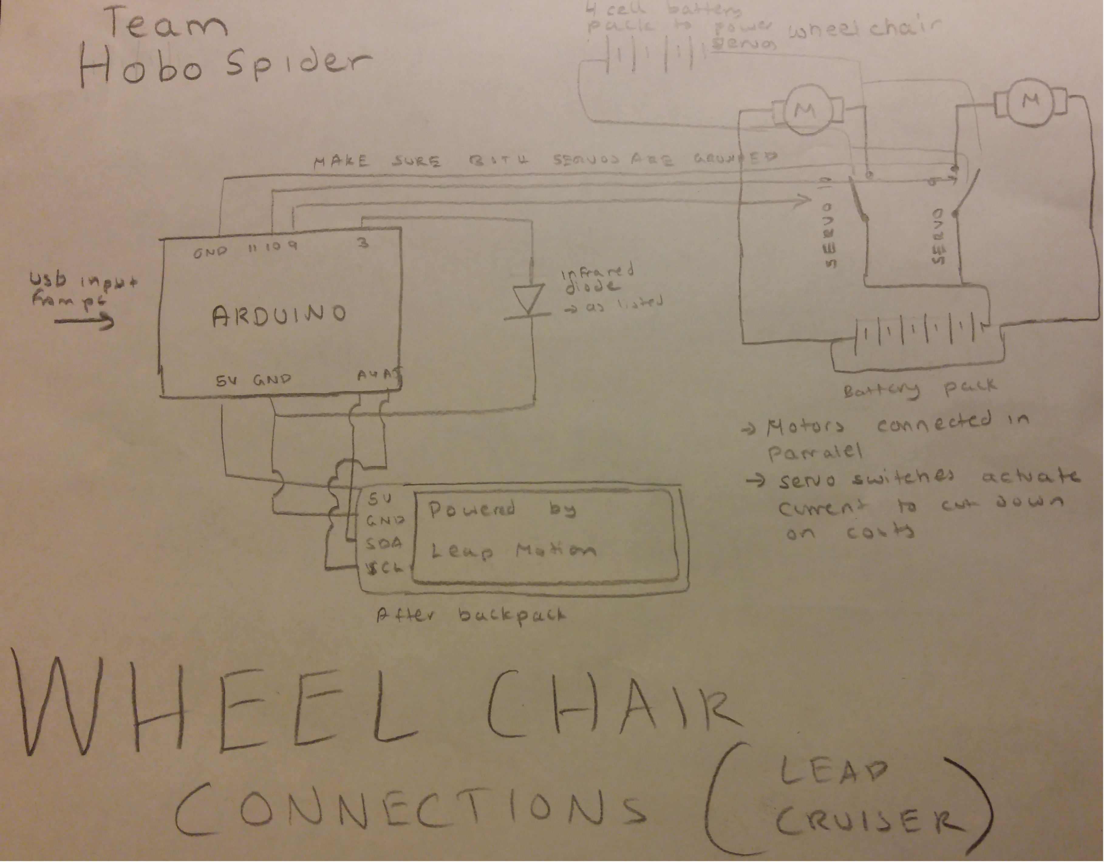
The leap motion sits below the arm rest of the wheelchair allowing the user to have their hand rest comfortably, unobstructed by joysticks or other physical controls. By default, the wheelchair starts in drive mode allowing the user to control their wheelchair by moving their fist fore and aft of the resting position. Turning is no more difficult, controlled by simple side to side motions of the wrist and/or arm. Moving your arm left turns the chair left and similarly, moving your arm right turns the chair right. The LCD displays the current menu the user in and by drawing a circle with their finger, they can cycle through the various menus, such as the light or TV control mode as seen in the demo. Within these auxiliary menus, the movement of the wheelchair is disabled and only the systems selected modes are active, allowing the user to control the programmed appliances with their respective gestures, removing any risk of accidental movement. All these actions are intuitive and feel completely natural. They can cycle through menus at any time giving them full control over their appliances and their wheelchair from a single unit.
HOW WE GOT TO WHERE WE ARE
After receiving the wheelchair from our grandparents friend, we stripped it down to the chassis and dc motors. After a quick test wire up, we discovered that the motors refused to spin regardless of current or voltage. Shortly after we noticed this problem, we began testing the two extra white wires that exited the motor body. We initially thought the wires were for a hall effect sensor to maintain constant rpms between motors but after some poking around we found that it was actually a form of a solenoid only releasing the brake when power is applied. After finding this out, we ripped them off the motor heads and the dc motors spun up perfectly.
Once we knew the drive system was functioning properly we began putting together the wiring system with some scrap heavy gauge single core wire we found laying around. From the batteries we made a crude y-splitter for the positive and negative leads to route power to each individual motor
For power control of each individual motor we took some of the heavy gauge wire and bent it into a u shape just above the motor mounts. We wanted to copy the design of the breakers used at large power stations because of its simplicity and cost effective nature. To make and break the connections we used two servos with a piece of a 8mm welding rod glued on to the horns. This would contact the u shaped wire completing the motor circuit giving us steering control.
After mounting the servos we needed to figure out how to get power from the contacted servo arms to the motors themselves. We wanted to make sure of the following criteria:
-Reduce cable strain as much as possible
-Remain reliable for long periods of time
-Reduce strain on the servos
To achieve the best compromise possible we mounted the wire to the end of the arm, making sure that the cable would never kink causing damage and unnecessary load on the servos. Though the extra leverage of the wire would cause more load for the servos it wasn't enough to warrant risking cable deterioration.
We then wired up servos, with just the right spacing so it would actuate the switch mechanism (8 mm welding rod contact to the u shaped connector). High current relays cost around 20 dollars each at a local electronics store, and since we would be needing two, the two servos for 4 dollars off eBay was the most cost efficient and simple. After hooking up the servos, we had to set contact points where the servo was sort of pushing into the connectors, but not enough that the servos were fighting (something to make sure of if your planning to replicate our project, the servos will get hot and strip if too much of a force is applied. i.e they can't be pushing too hard against a barrier). With a bit of trial and error we found the happiest spot for the servo contact.
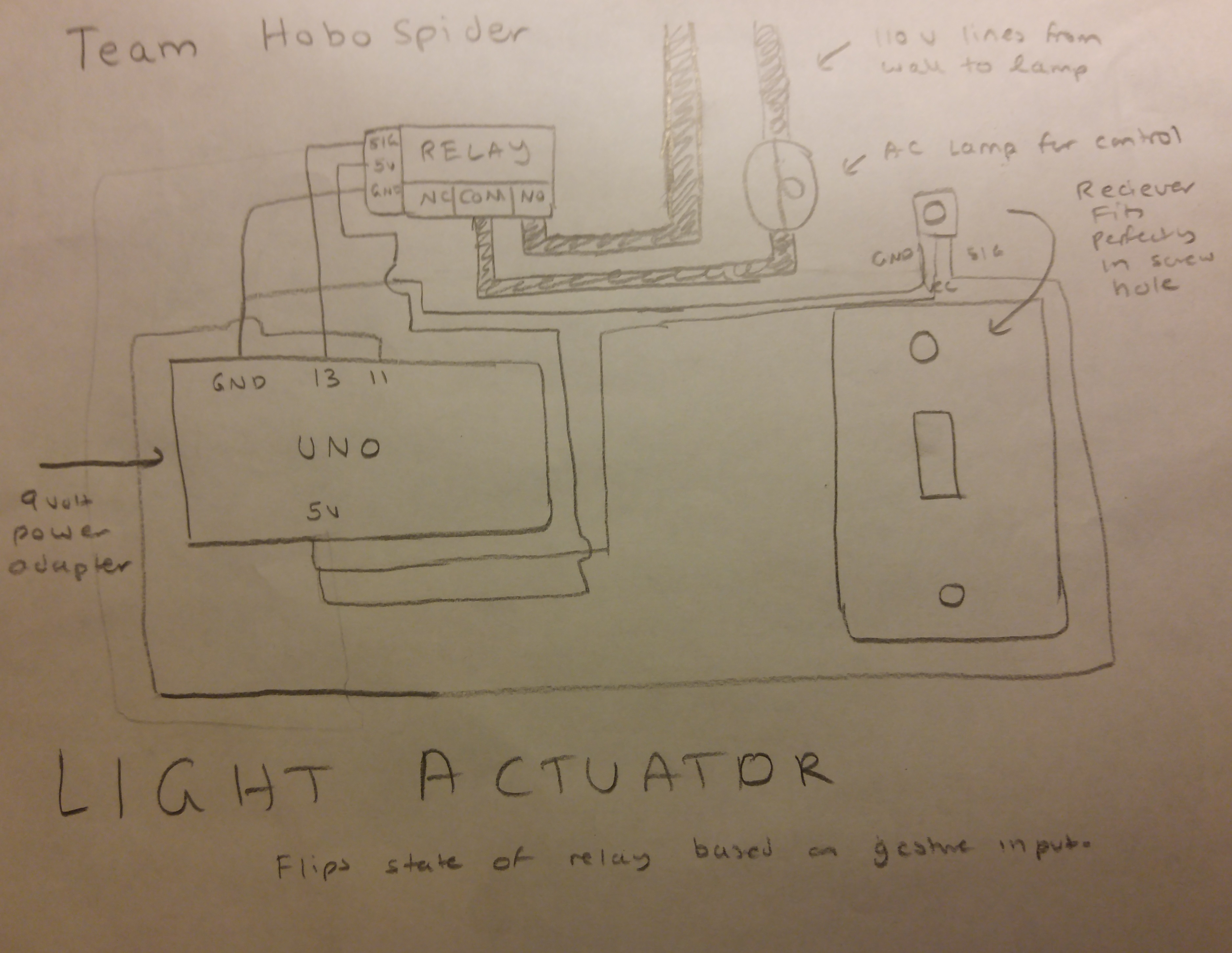
Now it was time to control the light. We hooked up the IR led (see diagram/schematic below) and routed it to the arm rest so appliance control will be intuitive. The IR led was pulled out of an old RC helicopter remote that no longer was functioning and had no purpose. After wiring this, we sent a few sample codes to our receiver and mapped it to the TV by matching the TV remote codes. Once the TV and light were functional through the Arduino we decided to move on to the processing code and testing phase with the leap motion.
We knew it was time to start testing the practicality of our idea. We began doing extensive tests on reliability and stability. We used Processing as our IDE and the code is given below with comments explaining how it works in general. Through our experimentation we found out various problems that we then fixed. After mapping the gestures of the leap motion to the appliance control and the wheelchair movement, we realized how much simpler it would be for the elderly to navigate and do things as everything is intuitive and easy to work with. Moving their hands and doing gestures to control the TV and other appliances is a lot easier than pressing buttons on a remote or a controller. It just simplifies their lives and without the leap motion this wouldn't be a possibility.
To further ease the control of appliances, we decided to add an LCD to show the menus that were available. A simple circle gesture clockwise would get it to move forward, and counter clockwise would get the menu to move backward. After adding this functionality, everything started to freeze and that was when we realized we had to streamline our code. So we made sure that the LCD only refreshes when the value changes allowing for the Arduino to still function without lagging or freezing.Type in a caption for this image
THE FUTURE OF OUR SYSTEM
Though we feel we have accomplished a lot with the project and reached many of the goals we set out for ourselves, we know we can take this project a lot further. We have many ideas we would like to implement but with us both being 17, lack the funding to do so effectively. Some of the ideas we would like to one day add are.
GPS TRACKING
Though the implementation of the link-it one unit we would be able to set out acceptable GPS locations for the user to be located within. these can include the home as well as standard routes taken by the user. if these location restrictions are broken for a given period of time a call may be sent out to the users family/ caretaker alerting them of the unexpected occurrence through the link-it ones sim card system. This system would also double as a theft identifying and tracking system.
ACTIVE HEART RATE MONITORING
While seated in the chair, heart rate may be monitored and recorded throughout the day. If an irregular or nonexistent heart rate is detected in conjunction with appropriate input characteristics (correct weight, no gesture input) The system may automatically contact EMS and activate an on-board microphone for communication if the trigger was accidental.
BLOOD SUGAR MONITORING AND INSULIN ADMINISTRATION
When seated in the chair users who suffer from type a/b diabetes may be granted the option to install a monitoring harness taking periodic blood sugar samples. The information from these samples may be relayed to the main control unit. From there, instructions can be sent to an insulin pump. By being able to actively monitor and administer insulin with complete autonomy users who may no longer be able to read write or understand the system can rest assured knowing that they are being monitored and taken care of with an accuracy far higher than any periodic self administration can achieve. If something was to go wrong and hypo or hyperglycemia was detected, care takers can be notified as a fail-safe.
IF YOU WOULD LIKE TO DO THIS YOURSELF
- The codes have been provided with their respective places.
- Follow the diagram for wiring
- Use trial and error to determine constants such as servo contact and release points
- Contact either of us for more help if necessary.


Comments
Please log in or sign up to comment.